7.2
All three torque equations, (6.17) through (6.19), of the induction motor in the stator reference frame include the difference-of-products terms. Notice that if, for example, in Eq. (6.18), \qr were made to equal zero, the resultant formula would be similar to that, (7.1), for the dc motor. Unfortunately, this is not possible, because Xqr constitutes the quadrature component of the revolving vector, of rotor flux. Thus, \qr = 0 is possible only if \ = 0, which is absurd.
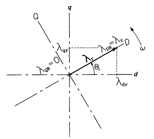
However, if torque equations in a revolving frame are considered, the manipulation described above becomes feasible. If
![tmp323-55_thumb[1] tmp323-55_thumb[1]](http://lh4.ggpht.com/_X6JnoL0U4BY/S1h110eQzlI/AAAAAAAAISw/xZLL87YSXDw/tmp32355_thumb1_thumb.png?imgmax=800)

FIGURE 7.2 Alignment of the revolving reference frame with the rotor flux vector.
![tmp323-57_thumb[1] tmp323-57_thumb[1]](http://lh5.ggpht.com/_X6JnoL0U4BY/S1h2B6VJV2I/AAAAAAAAITA/-fa6EOEXp1Y/tmp32357_thumb1_thumb.png?imgmax=800)
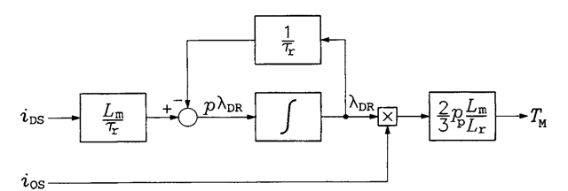
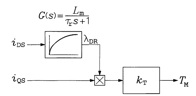
Based on the dynamic equations of the induction motor, a block diagram of the field-oriented motor in a revolving reference frame aligned with the rotor flux vector is shown in Figure 7.3. According to the theory of linear dynamic systems, the integrator block with negative feedback can be replaced with a first-order block, as shown in Figure 7.4. It can be seen that the torque in a field-oriented motor reacts instantly to changes in the ?qS component of the stator current, while the reaction of rotor flux to changes in the other component, /Ds> is inertial.

FIGURE 7.3 Block diagram of the field-oriented motor in a revolving reference frame aligned with the rotor flux vector.

FIGURE 7.4 Reduced block diagram of the field-oriented motor in a revolving reference frame aligned with the rotor flux vector.
![tmp323-60_thumb[1] tmp323-60_thumb[1]](http://lh4.ggpht.com/_X6JnoL0U4BY/S1h2L-EgijI/AAAAAAAAITc/q9F5Hr3nRJ0/tmp32360_thumb1_thumb.png?imgmax=800)
PRINCIPLES OF FIELD ORIENTATION (Induction Motor)
Next post: DIRECT FIELD ORIENTATION (Induction Motor)
Previous post: TORQUE PRODUCTION AND CONTROL IN THE DC MOTOR (Induction Motor)
