Bullet deformation during ballistic impact (semi – infinite steel plate impact test)
The objective of this experiment is to capture bullet dynamic deformation while impacting a hardened steel block (Taylor test) [6]. The test setup consists of a light source illuminating the prjectile’s side, while impacting the steel block, and two high speed cameras capturing images of the projectile deformation during the impact. Figure 14 shows a schematic of the experimental set up. While back camera serves to ensure straightness of the impacted bullet (Figure 15), side camera images (shown in Model validation paragraph, Figures 20 and 21) are used to determine projectile deformation during the impact.
Fig. 14 Test setup
Fig. 15 Back camera view of a bullet impacting steel block
NUMERICAL
To determine the elastic and inelastic material properties of the material, numerical simulations of the quasi-static (1 s-1 strain rate) and moderate strain rate (100 s-1) compression tests of bullet components (core and jacket) were performed using ABAQUS/Explicit.
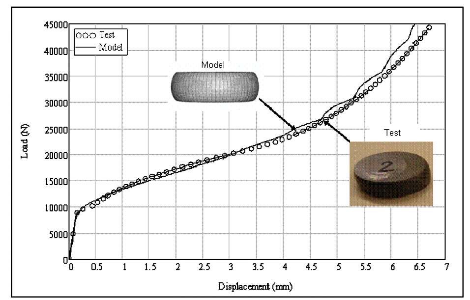
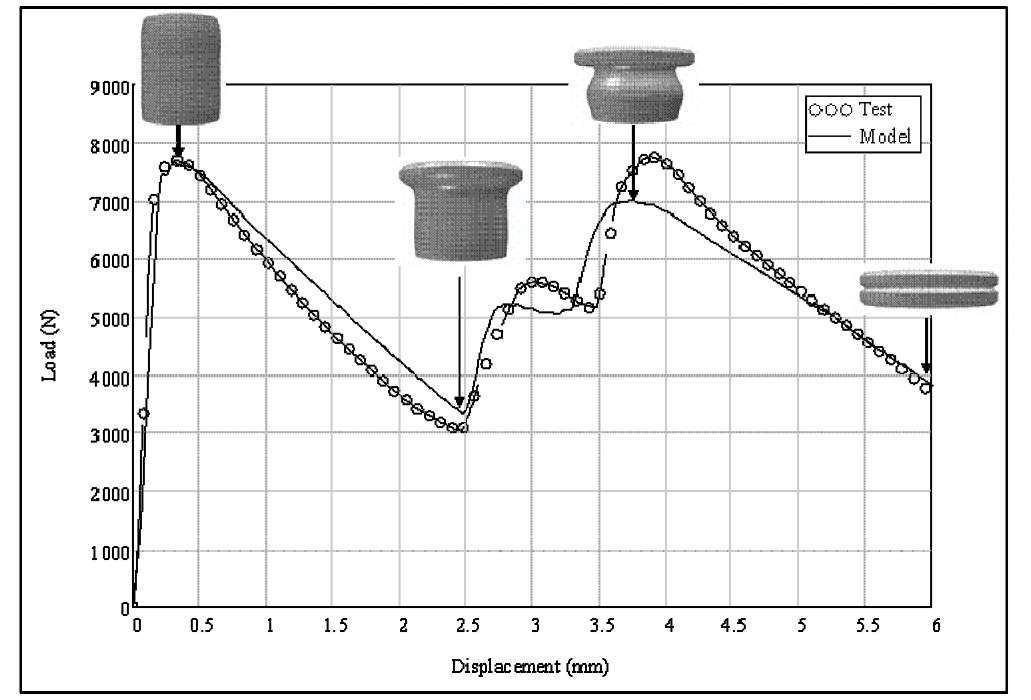
The jacket model was compressed between two flat rigid plates that represent the boundary condition in the compression test. The ABAQUS/Explicit general contact algorithm was employed. The bottom plate was fixed in space and the bottom of the component was in contact with the bottom plate. The top plate moved slowly, compressing the specimen, to simulate the strain rate of 1 s-1 and 100 s-1. A similar modeling approach was used to simulate the core and bullet compression tests (Figures 16 and 17). Initial literature values for common material were used and load-deflection curve from the simulation were compared to the experimental load-displacement curve. The material properties were determined through an iteration process in which the load-deflection curve of the model with the best fit for the experimental load-displacement curve was chosen.
Fig. 16 Test and Model – Core
Fig. 17 Test and Model-Jacket (with the model deformation modes)
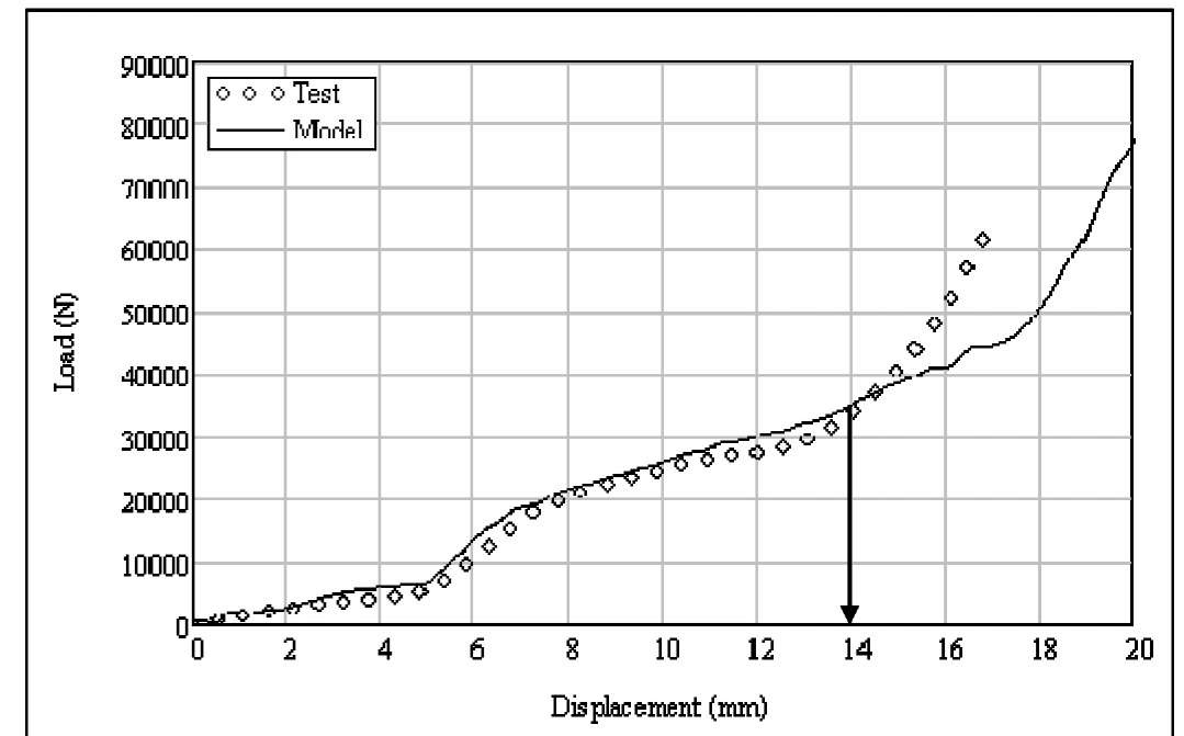
The second set of simulations included the model of a whole bullet under quasi-static (1s-1) and moderate (100s-1) strain rate (MSR) compression test using the material properties developed with the numerical simulation of the individual bullet components (Figure 18). Note that comparison of the test and model is not valid after 14mm of compression. After that point tested bullets would start to buckle, therefore assumed perfect symmetry of the model is not applicable any more. The objective was to refine the constitutive and damage models for the materials and the structural response of bullet.
Fig. 18 Force-Displacement MSR Test and Model
The final numerical simulation was of bullets impacting a semi-infinite rigid plate over a range of impact velocities. The predicted failure modes and deformed shapes were compared to the experimental results. The objective was to obtain an accurate representation of bullet response during ballistic impact.
Description of the model
A numerical simulation of the compression test requires a 3D model of the bullet. Three-dimensional linear brick elements with reduced integration were used. FE model characteristics are listed in Table 2. The bullet and bullet components are symmetrical. Consequently, only a quarter of the specimen tested with a symmetric boundary was considered. The component models represent the exact dimensions, geometry and loading conditions as the specimen tested.
Table 2 7.62x39mm MSC FE Model characteristics
|
Element Type |
C3D8R |
|
|
Number of elements |
jacket |
2487 |
|
core |
2148 |
|
|
filler |
1704 |
|
|
Adaptive mesh |
Yes |
|
|
Hourglass control |
Enhanced |
|
|
Bulk Viscosity |
0 |
|
|
Kinematic formulation |
Orthogonal |
|
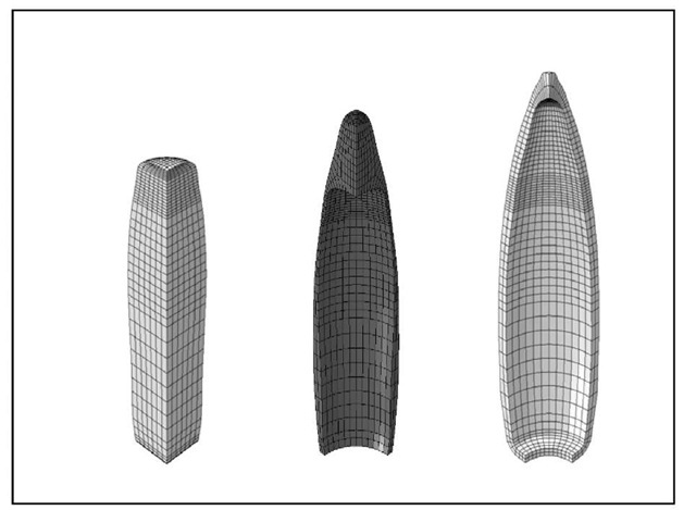
The bullet geometry determined by the coordinates on profilometer (Figure 3 and 4) was used to create the non-linear finite element model of the jacket, filler and core of the bullet (Figure 19).
Fig. 19 Bullet Model (core, filler and shell)

