Material Constitutive Model
In general, the response of material under high-speed impact involves consideration of the effect of strain, strain rate and temperature.
The Johnson-Cook material model with strain rate dependence [4] was used in the simulation to define the inelastic behavior of the bullet materials.
The static yield stress, ao, is assumed to be of the form
Where
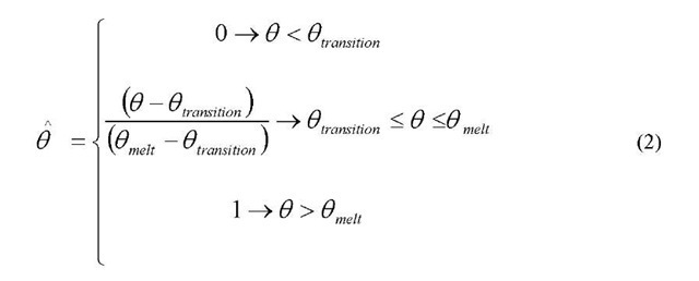
 is the equivalent plastic strain and A, B, n and m are material parameters measured at or below the transition temperature 0 transition. 6 is the non-dimensional temperature defined as
Where 0 is the current temperature, 0 meit is the melt temperature and 0 transition is the transition temperature defined as the one at or below which there is no temperature dependence on the expression of the yield stress.
The Johnson-Cook strain rate dependence assumes that
And
Where
![]() yield stress at nonzero strain rate
yield stress at nonzero strain rate
![tmp1A0530_thumb[2] tmp1A0530_thumb[2]](http://what-when-how.com/wp-content/uploads/2011/07/tmp1A0530_thumb2_thumb.jpg) equivalent plastic strain rate
equivalent plastic strain rate
C: material parameters measured at or below the transition temperature
![tmp1A0533_thumb[2] tmp1A0533_thumb[2]](http://what-when-how.com/wp-content/uploads/2011/07/tmp1A0533_thumb2_thumb.jpg) is the ratio of the yield stress at nonzero strain rate to the static yield stress (so that
is the ratio of the yield stress at nonzero strain rate to the static yield stress (so that
The elastic behavior of the material was defined with a hydrodynamic material model, in which the pressure is defined as a function of the density and the internal energy.
Two different dynamic failure models were used in the numerical simulation.
The ABAQUS/Explicit Johnson-Cook dynamic failure model was used for the lead material, since the filler of the 7.62×39 mm Mild Steel Core (MSC) bullet are made out of lead.
The ABAQSU/Explicit progressive damage and failure model was used for the steel material, in order to simulate the core and jacket of the 7.62×39 mm Mild Steel Core (MSC) bullet that are made out of steel.
Dynamic Failure Model for Lead Material
The Johnson-Cook dynamic failure model [5] which is suitable for high-strain rate deformation of metals was used to define the lead failure in the high speed ballistic impact simulation. This dynamic failure mode is available in ABAQUS/Explicit.
The model assumes that the equivalent plastic strain at the onset of damage,![tmp1A0535_thumb[2] tmp1A0535_thumb[2]](http://what-when-how.com/wp-content/uploads/2011/07/tmp1A0535_thumb2_thumb.jpg) is a function of stress triaxiality and strain rate. The failure is assumed to occur when the damage parameter exceeds 1. The damage parameter, ra, is defined as
is a function of stress triaxiality and strain rate. The failure is assumed to occur when the damage parameter exceeds 1. The damage parameter, ra, is defined as
Where
![]() is an increment of the equivalent plastic strain,
is an increment of the equivalent plastic strain,![]() is the strain at failure, and the summation is performed over all increments in the analysis. The strain at failure,
is the strain at failure, and the summation is performed over all increments in the analysis. The strain at failure,![]() is assumed to be dependent on a non-dimensional plastic strain rate,
is assumed to be dependent on a non-dimensional plastic strain rate,
![tmp1A0541_thumb[2] tmp1A0541_thumb[2]](http://what-when-how.com/wp-content/uploads/2011/07/tmp1A0541_thumb2_thumb.jpg) ; a dimensionless pressure-deviatoric stress ratio, p/q, where p is the pressure and q is the Mises stress; and the non-dimensional temperature d . The dependencies are of the form
; a dimensionless pressure-deviatoric stress ratio, p/q, where p is the pressure and q is the Mises stress; and the non-dimensional temperature d . The dependencies are of the form
Where d1 to d5 are failure parameters measured at or below the transition temperature.
Dynamic Failure Model for Steel Material
ABAQUS/Explicit offers a general capability to predict progressive damage and failure. The capability supports the specification of damage initiation criteria and damage evolution.
The Johnson-Cook damage criterion was used in the simulation, which is defined in equation (7).
The damage evolution was based on effective plastic displacement, which is defined with the evolution equation
where L is the characteristic length of the element
Table 3 Bullet Material Properties
|
Johnson – Cook Plasticity Material Model |
|||||
|
Bullet Component |
A [MPa] |
B [MPa] |
n |
m |
C |
|
7.62x39mm MSC-core |
234.4 |
413.8 |
0.25 |
1.03 |
0.00333 |
|
7.62x39mm MSC-jacket |
448.2 |
303.4 |
0.15 |
1.03 |
0.00333 |
|
Lead-filler |
10.3 |
41.3 |
0.21 |
1.03 |
0.00333 |
|
Johnson – Cook Dynamic Failure Model |
|||||
|
Bullet component |
d1 |
d2 |
da |
d4 |
d5 |
|
Steel core |
5.625 |
0.3 |
-7.2 |
-0.0123 |
0 |
|
7.62x39mm MSC-jacket |
2.25 |
0.0005 |
-3.6 |
-0.0123 |
0 |
|
Lead filler |
0.25 |
0 |
0 |
0 |
0 |
Damage Evolution Type displacement =0.0001
Mie-Gruneisen Equation of State (used on all the materials)
c0= 4.569E6 mm/s s=1.4 1^=1.93
Linear Elastic Shear Modulus G = 9.446E3 MPa
Validation of Numerical Model
A series of high speed ballistic impact test simulations were performed for bullets with velocities ranging from 120 m/s to 600 m/s. The ABAQUS/Explicit general contact was employed to simulate contact between the projectile and the plate. This contact algorithm was also used to simulate the interaction between the different bullet components, such as the interaction between the core and jacket and/or interaction between core, filler and jacket. During the bullet impact, the petals that developed bend until they come into contact with the hardened steel plate. The self-contact algorithm was used to consider this interaction.
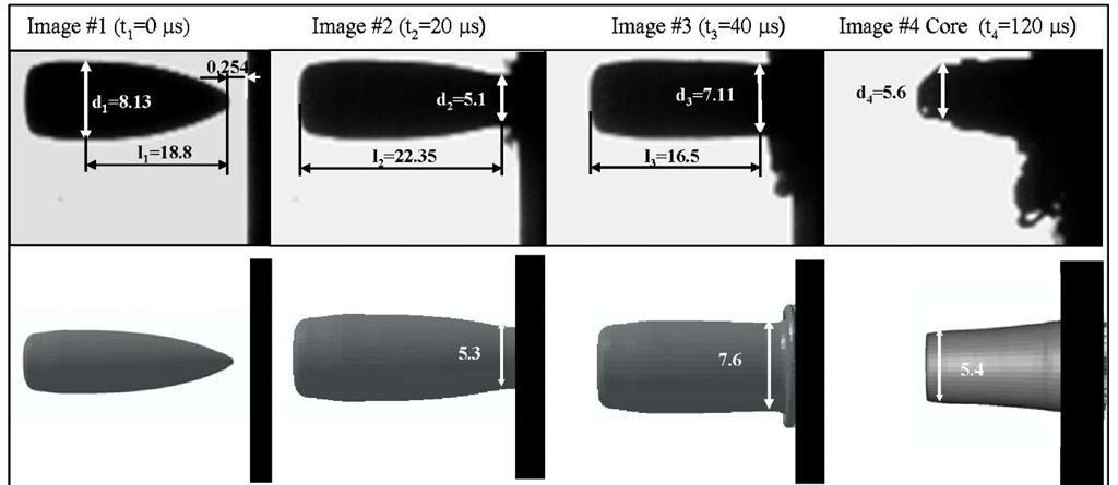
Fig. 20 A comparison of projectile side view impact and numerical simulation of an MSC Bullet traveling at 253 m/s and impacting a hardened steel plate (all dimensions in mm)
Fig. 21 A comparison of projectile side view impact and numerical simulation of an MSC Bullet traveling at 562 m/s and impacting a hardened steel plate (all dimensions in mm)
Figures 20 and 21 show a comparison between the experiment and the model of a bullet impacting steel plate at 253 m/s and 562 m/s, respectively. It can be seen that the model accurately represents deformed shapes and failure modes.
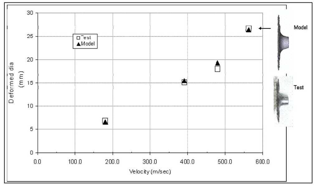
The predicted versus actual bullet diameter change for a range of velocities are plotted on Figure 22. Again, the predicted bullet deformations are in good correlation with the measured diameter change.
Fig. 22 A comparison of maximum deformed diameter of bullet after impacting a hardened steel plate and numerical simulation of an MSC bullet traveling at various velocities and impacting a hardened steel plate
CONCLUSION
In order to develop a constitutive and damage models of 7.62×39 mm mild steel core (MSC) bullet for nonlinear FE analysis, series of mechanical experiments are performed on bullet and bullet components, including quasistatic and moderate strain rate compression tests. Exact geometry and dimensions of each bullet’s component is obtained using profilometer. Numerical simulations of a bullet impacting a semi-infinite rigid plate are carried out over a range of impact velocities, and the predicted failures modes and deformed shapes compared to experimental results obtained using high speed cameras. It was found that the models, implemented in ABAQUS Explicit, were able to accurately predict deformed shapes and failure modes without any predefined defects in the element mesh. These validated models form part of a growing set of tools within DuPont to study energy absorption and dissipation mechanisms during the ballistic impact of fibrous armor. This in turns should help with the design of better armor structures such as helmets, small arm protection inserts and vehicle armor.


![tmp1A0531_thumb[2] tmp1A0531_thumb[2]](http://what-when-how.com/wp-content/uploads/2011/07/tmp1A0531_thumb2_thumb.jpg)
![tmp1A0532_thumb[2] tmp1A0532_thumb[2]](http://what-when-how.com/wp-content/uploads/2011/07/tmp1A0532_thumb2_thumb.jpg)
![tmp1A0534_thumb[2] tmp1A0534_thumb[2]](http://what-when-how.com/wp-content/uploads/2011/07/tmp1A0534_thumb2_thumb.jpg)
![tmp1A0537_thumb[2] tmp1A0537_thumb[2]](http://what-when-how.com/wp-content/uploads/2011/07/tmp1A0537_thumb2_thumb.jpg)
![tmp1A0542_thumb[2] tmp1A0542_thumb[2]](http://what-when-how.com/wp-content/uploads/2011/07/tmp1A0542_thumb2_thumb.jpg)
![tmp1A0543_thumb[2] tmp1A0543_thumb[2]](http://what-when-how.com/wp-content/uploads/2011/07/tmp1A0543_thumb2_thumb.jpg)


