Keywords: Dynamic cracking, Ultra-high speed camera, Digital Image Correlation, Spalling test.
Abstract
The dynamic crack velocity is a key-parameter involved in the micro-mechanics based modelling of the tensile damage of geomaterials under impact loading. However, because of technical difficulties, very few experimental methods have been proposed in the literature. In this work, a new set-up is presented based on spalling tests. A compressive pulse is transmitted to a parallelepipedic specimen by means of a Hopkinson bar. It is reflected as a tensile wave on the opposite free surface of the sample. A short notch is used to trigger a single crack whereas a larger notch provides a rocking effect of the rear part of the specimen. This experimental configuration has been optimized using numerical simulation analysis. Finally, a series of tests have been conducted on dry and wet concrete. Crack gauges and ultra-high speed camera coupled to Digital Image Correlation have been used to determine the crack speed in this material.
Experimental set up
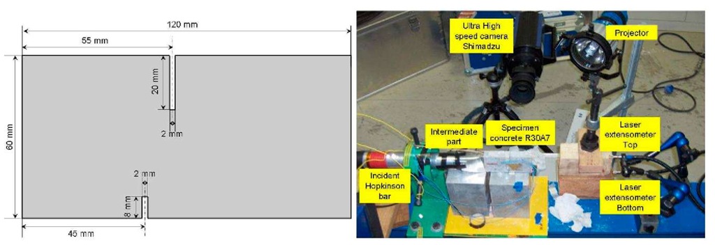
A gas gun launches a projectile made of aluminium alloy 65 mm in length and 45 mm as diameter that hits the Hopkinson bar of the same diameter and 1200 mm length, Fig.1 -right. The pulse is then transmitted to the specimen which has been put in contact with the bar. An ultra-high speed camera is used to visualize the crack propagation during the test. This camera has a 312×260 pp resolution and is able to acquire 102 images with an inter-frame time up to 1 micro-second. In addition, because of the rocking effect of the specimen two lasers interferometer are placed pointing on the rear edge of the specimen, one on the top of the rear edge and the other on the bottom. A series of numerical modeling has been conducted to optimize the design of the specimen and the projectile velocity with the aim to increase the stress intensity factor for triggering the crack without damaging the target. The specimen, Fig.1 -left, is parallelepipedic 120x60x20 m3. Each sample is pre-notched to favour the crack initiation. Also, a high density random pattern is applied to the filmed face of the specimen in order to perform a Digital Image Correlation post-treatment [1]. Moreover, a strain gauge is placed close to the contact edge for recording the transmitted pulse and a crack gauge is stucked on the opposite face close to notch tip, where the crack initiation is expected, to characterize the crack propagation.
Fig.1: Optimized specimen geometry used in the rocking spalling tests (left). Experimental set up used for dynamic crack propagation testing (right).
Experimental results
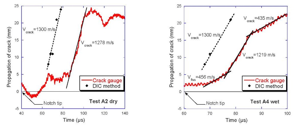
Seven tests have been performed with two sets of sample: water saturated specimens and dried specimens. The dried specimens others were stored at 65°C unti l they reached a stabilized mass. Two results are plotted in Fig.2 for dry and wet specimens. Both tests show a gap in time regarding the crack initiation between the crack gauge signal and the DIC results. It is supposedly due to a lack of resolution of the crack gages. Nevertheless, a consistent value of crack propagation velocity has been found out (1300 ms-1).
Fig.2: Crack velocity in R30A7 concrete: comparison between crack gauge and DIC results for dry specimen (left) and wet specimen (right).
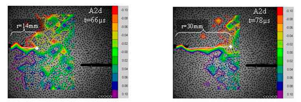
Crack propagation with DIC is determined from an analytical method [2] based on the Crack Opening Displacement measurements. This method allows evaluating the crack tip position (Fig.3) and cracking velocity, (Fig.2).
Fig.3: Axial displacement field (vertical orientation on figure) in pixel measured by DIC for dry specimen A2 (Correli Q4 software, 1 pixel = 0.1923 mm). Estimation of the crack tip position for t = 66 ^s and t = 78 ^s.
Conclusion
This work presents a new experimental methodology named Rocking Spalling test performed to determine the crack propagation velocity in concrete materials. Technical difficulties related to single crack initiation problems have been analysed numerically. Crack velocity has been measured by crack gauge and Digital Image Correlation. The latter gives more accurate results for this material.


