Abstract
Modern factory-built windows and window components are available which can greatly reduce that portion of building energy consumption attributable to the windows. The adverse energy consequences of using larger window apertures for good daylighting (thereby realizing its attributes) can be reduced or even eliminated. The result can be buildings with greater comfort, more productive occupants, and substantially reduced purchased energy costs. As we pass the peak of world oil production and approach peaks in other fossil-fuel supplies, considerable energy and dollar savings are possible through the use of the new high performance windows.
INTRODUCTION
Windows have been included in building envelopes since the first buildings were constructed—mainly for the illumination and view that they provide. The addition of glazing provided increased protection from wind and rain. In the past, windows were considered “holes in the insulation.” As a result, window areas have generally been kept modest in size, especially in buildings designed for hot or cold climates. Modern window designs and materials have made it possible to minimize—and, in some cases, avoid altogether—the energy costs of windows, enabling builders to utilize larger areas for aesthetic, viewing, and health benefits. In some circumstances, good windows can outperform opaque insulated walls, energy-wise.
The energy performance of a building’s window system can be estimated through a variety of engineering calculations. Due to the vagaries of weather and climate, these measures are best performed with the aid of computer simulation, wherein the hourly energy and illumination performances of windows can be assessed quickly with modest precision. In window design, care must be taken to ensure strong energy performance sans excessive glare, overheating, or thermal discomfort.
This article examines the fundamentals of window energy performance and presents some issues surrounding window and shade design and product selection. A separate chapter discusses daylight design more generally.
FUNDAMENTAL QUANTITIES
Radiant flux, $, is the time rate of radiant energy flow (unit: watt).
Irradiance, E, is the radiant flux per unit area at a specified point in a specified surface that is incident on, passing through or emerging from that point in the surface, or the average of this quantity over the surface’s area (units: watt m”2).
Conductive heat flow, Q, is the flow of heat through a specified distance in a material per unit area and per unit temperature difference. It has units of energy flux per unit area and per unit temperature difference (units: Wm~ 2K ”
An important characteristic of radiant flux is its distribution over the electromagnetic spectrum, known as a spectral distribution or spectrum. The Greek symbol A is used to symbolize the wavelength of monochromatic radiation, defined as radiation with only one frequency and wavelength. The symbol for frequency is the Greek symbol v. The relationship between frequency v and wavelength A is shown in the equation
Xv = c (l)
where c is the speed of propagation in the medium (more familiarly, the “speed of light,” even though “light” is properly applied only to the visible portion of the spectrum). The spectral concentration of radiant flux at a given wavelength A is given the name “spectral radiant flux” and represented by the symbol $^ (units: W nm~The wavelength dependence is represented by the functional notation, thus, 3>;i(A), where the subscript denotes the concentration of the quantity at a specific wavelength.
Spectral irradiance is the spectral “concentration” of the irradiance E, and its wavelength dependence is denoted by the symbol E-A(A) (units: W m~2 nm~
Names for the relevant regions of the electromagnetic spectrum are provided in Table 1.[1]
ENERGY BASICS
Heat Transfer
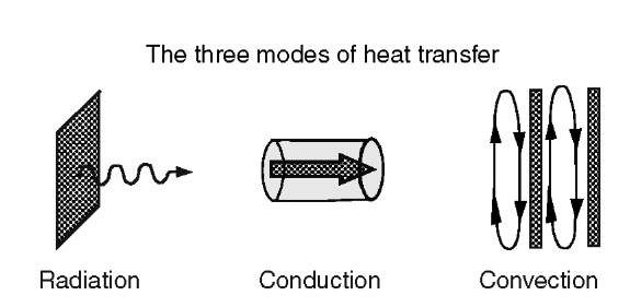
Energy is transferred through windows by the three mechanisms: radiation, conduction, and convection, illustrated in Fig. 1.
Table 1 CIE vocabulary for spectral regions
| Name | Wavelength range |
| UV-C | 100-280 nm |
| UV-B | 280-315 nm |
| UV-A | 315-400 |
| VIS | Approx. 360-400 to 760-800 nm |
| IR-Aa | 780-1,400 nm |
| IR-B | 1.4-3.0 nm |
| IR-Cb | 3 (im-1 mm |
aAlso called “near IR” or NIR. bAlso called “far IR” or FIR.
Radiation Heat Transfer
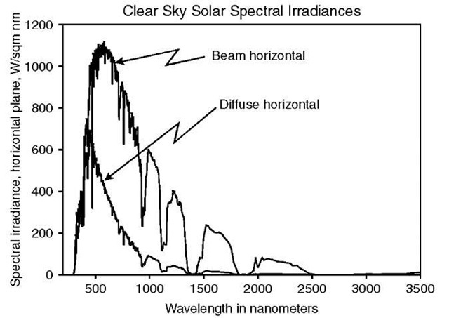
The primary form of radiative heat transfer through windows is solar energy. Irradiance spectra for the sun and the diffuse sky for a clear day are shown in Fig. 2.
All objects above an absolute zero temperature emit radiation. Those with temperatures much cooler than the sun emit radiation in the far IR (FIR) region. Radiative transfer can also occur in windows over this spectral band. The FIR region is separated significantly from that of the solar spectrum.[2]
The spectral separation between solar and FIR radiation makes the greenhouse effect possible, a process whereby solar radiation is transmitted effectively through clear glass, but the longer-wavelength radiation emitted from objects receiving the transmitted solar radiation does not transmit back through the glass easily. This mechanism enables greenhouses to remain warm on cold winter days when they receive ample solar radiation, without the need for additional heating. Window manufacturers have learned to take advantage of this spectral separation to improve the winter day and night performance of glazing systems for a variety of applications. When it is cold outside and warm inside, significant quantities of FIR radiation can pass from the warm inner glazing across the gas gap in a double pane window to a colder outer pane. Several mechanisms, described below, are available for reducing the magnitude of this component of heat loss through windows.
Fig. 1 The three modes of heat transfer.
Fig. 2 Spectral irradiance distributions for clear sky direct beam and diffuse sky radiation on a horizontal plane.
Conduction Heat Transfer
Heat is transferred via conduction through material that has at least two surfaces with different temperatures. The heat conducts through the material from the warm surface to the cooler one. The rate of transfer depends upon the magnitude of the temperature difference and the thermal conductivity of the material, k, having units of energy per unit time, per unit area, per unit distance through the material, and per unit temperature difference. For homogeneous materials of specific thickness t, the conductance C of that thickness is a product of the conductivity of the material and the distance t through it. Conductance has units of energy per unit time, per unit area, and per unit temperature difference. Window frames with sections that have lower thermal conductivity are more insulating than those without these thermal breaks. Generally, the thermal resistance R is the reciprocal of the thermal conductance C.
Convection Heat Transfer
A warm surface can transfer some of its heat to the adjacent air by conduction . Once the air in a thin film adjacent to the surface receives this heat, it expands slightly and there is a tendency for the air to rise. This air movement can carry heat to or from the glazing of a single-pane window. If the surface is a vertical one, and if the rising warmed air reaches a boundary (like the window frame around an insulating gas space between the panes of a double pane window), it tends to move laterally. If there is a cooler vertical second pane, the heated air will tend to move downward. As it descends, it will lose some of its heat via conduction into the cooler pane of glass. The higher density of the cooler air will drive it further downward and it will, at the bottom, move laterally from the cooler toward the warmer surface, filling the space left by the less dense, rising air next to the warmer pane of glass. This circulation of air from a warmer pane to a cooler one provides the third mechanism for heat transfer through a window—convection.
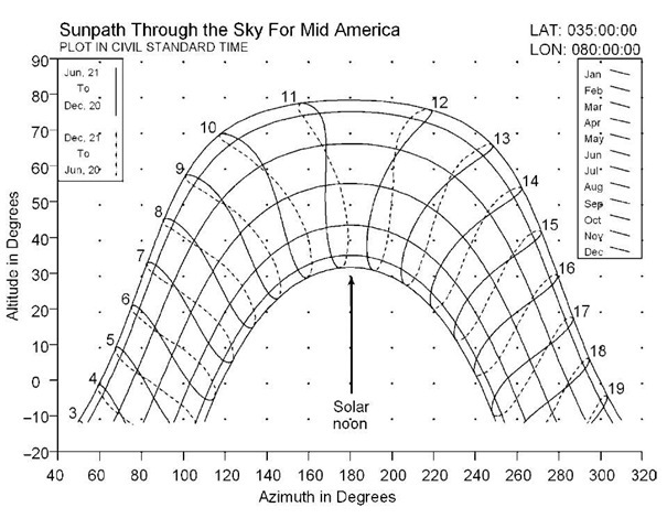
Fig. 3 Sunpath chart for a central U.S. location, in local standard time. Due south is at azimuth 180°. East is at 90°.
Air adjacent to a warm pane thus convects to the cooler pane, releases its heat, and repeats the cycle. See Fig. 1. If the air were not moving, it would be a relatively effective insulator since the conductivity of air at atmospheric pressure is quite small. Convective movement of air, however, can “short-circuit” the insulating value of still air and promote heat transfer. Changing the gap width affects the rate of heat transfer by convection. Generally, there is a non-zero optimum gap width for a given gas that maximizes the thermal resistance due to convection.
Double pane windows generally have substantially lower conduction and convection heat transfer. In climates with modest year-round inside/outside temperature differences, single pane windows may be adequate. Multiple pane windows exhibit significantly lower energy costs on buildings in climate regions that experience significant inside/outside temperature differences.
THE PATH OF THE SUN THROUGH THE SKY
The sun moves in a predictable manner each day. During the winter in the northern hemisphere at middle latitudes, it rises south of due east (azimuth 90) and sets south of due west (azimuth 270). In the summer, it rises north of due east and sets north of due west. Plots of solar position vs time on a chart of solar coordinates form what is called a sunpath chart. Fig. 3 shows an example of a sunpath chart for latitude 35 degrees north and longitude 80 degrees west. A variety of sunpath calculators are available on the Web.
ORIENTATION AND SHADING
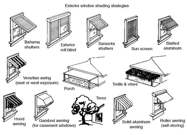
If the paths of the sun for a given location are known, the building and its windows can be oriented to either capture or prevent the entry of solar heat gain from the direct sun and/or diffuse sky light. Shading devices of many kinds can also be applied to the building to block direct solar beam entry. A variety of devices for exterior application are illustrated in Fig. 4.
Interior shades can also be effective if their solar reflectances on the window-facing side are high, thereby causing them to reflect most of the solar radiation incident back toward—and hopefully through—the window to the outside.
Solar heat loading on cooling equipment can be further reduced when desired by placing buffer spaces like garages, laundry rooms, warehouse space, porches, and utility rooms on the east- or west-facing sides of a building.
When passive solar space heating is desired, moderately large window areas can be added to facades that face directions from which strong direct solar radiation can be expected during certain seasons of the year and times of day. This solar gain can be moderated by judicious building and window orientation and through the use of exterior shading devices and vertical and horizontal fins and overhangs designed to selectively shade the window when direct sunlight is not desired.
Fig. 4 Window shading options illustrated. Credit: Florida Solar Energy Center, 1679 Clear lake Rd., Cocoa, FL 32922.
Direct beam entry into a building should be carefully facilitated due to the potential adverse consequences that can result. Bright spots in a generally darker room can be powerful sources of glare and should therefore be avoided or carefully moderated by architectural or interior design features. Localized overheating and the fading of interior furnishings are additional difficulties that can be produced by direct beam entry. Both exterior and interior shades, properly operated through either manual or automatic motorized control, can be effective means of reducing glare and controlling direct beam solar heat gain, while still allowing unobstructed views of the exterior when the sun is not a problem.
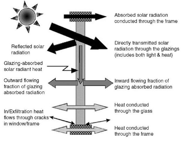
Fig. 5 Heat flows through window glass and window frames.
WINDOW HEAT TRANSFERS
Solar radiant heat is conducted through a window via several mechanisms, depicted schematically in Fig. 5.
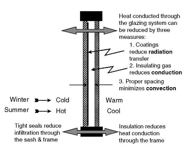
The thermal conductivity of glass is typically about 1.5 Wm~”\ Transparent acrylic and polycarbonate plastics are sometimes used as glazing materials, and their conductivities (around 0.2 Wm~ “are somewhat lower than that of glass, but the inherent thermal conductivity of air in the absence of convection is approximately 0.002 Wm~ ” \ a much lower value. Double pane windows with a correctly sized gas gap can therefore significantly reduce the conductive heat transfers through them. Use of a more insulating gas, such as Argon or Krypton, can further reduce conductive heat transfer through windows. Due to convection, however, the thermal resistance of the gas gap is somewhat less than the conductance of still air (or a more insulating gas) with the same gap thickness.
All objects above absolute zero emit radiation. Long-wavelength infrared radiation (often termed “thermal” radiation) is therefore another mechanism of heat transfer in windows (the net heat transfer being from a warm to a cold surface). At the temperatures encountered in glazing systems, this radiation is invisible; it is confined to the long-wavelength (FIR) region of the electromagnetic spectrum.
The combined effects of conduction, convection, and radiation across the gas gap between glazing panes, which results from the temperature difference between inside and outside air, are often lumped together in colloquial descriptions and given the name “conductivity.” A double pane glazing system has two panes separated around the edge by a spacer bar, a structural material that keeps the panes the correct distance from one another. The spacer bar is often made of metal to ensure its strength. The higher thermal conductivity of metal results in higher conduction of heat through the glass/spacer/glass edge than through the center of the glass/gas/glass combination. Insulated glazing units (IGUs) usually have an edge seal around the outside perimeter of the unit. Sealant is often used between the glass and spacer bar, as well.
To prevent condensation inside sealed IGUs, a desiccant material is usually incorporated into the spacer bar, which contains small openings to allow water vapor in the gas gap to be absorbed by the desiccant inside. Some spacer bars are made of materials with higher insulating value to reduce conduction transfer, or they may contain a thermal break, a section of non-metallic, lower conduction material.
The glazing system is set within a frame. The total window unit, including the glazing and frame, is called a sash. The sash fits into another frame that is connected to the wall and holds the sash in place. Due to its use of different materials, the frame around a glazing conducts heat differently from the glazing. The National Fenestra-tion Rating Council, responsible for rating the energy performance of windows and other fenestrations in the U.S., requires different values for the combined con-ductive/convective/FIR radiative transfer of heat through the center of a glazing system, through its edge, and through the framing members surrounding the glass.[3] The total thermal conductance of the entire sash is an area-weighted average of the frame, edge, and center of the glass values. Frames made of metal often contain thermal breaks to reduce conduction heat transfer through them.
If a window has cracks or other openings that permit the flow of air through these openings between the inside and outside of the building, the air so transferred can carry heat with it, thereby reducing the thermal integrity of the window. Such convective heat flow is termed infiltration or exfiltration, depending upon whether the air is flowing from outside to inside or vice versa. Modern factory-built windows generally exhibit relatively little infiltration and the heat gains or losses via this mechanism are generally much smaller than other heat transfers through the window. Windows in very cold areas, such as close to the poles of the Earth during the winter, can be exceptions to this rule if they are not very carefully constructed to minimize infiltration transfers.
In hot climates and buildings with air cooling equipment, the infiltration of hot and humid outside air poses a special problem. The air conditioner has to both cool the air and remove some of its moisture. At times, it takes more energy to remove the moisture (called a latent cooling load) than to lower the air’s temperature (called a sensible cooling load). Windows, such as “jalousie” windows with large infiltration openings, often contribute large latent and sensible cooling loads to the building. Repairing or replacing such windows would be a useful energy conservation strategy.
THE “U-FACTOR”—CONDUCTIVE HEAT TRANSFER
The American Society of Heating, Refrigerating, and Air Conditioning Engineers (ASHRAE) uses the term “U-factor” to designate the overall conductive transfer property of a window: the heat transferred through the window by virtue of the temperature difference between the inside and outside air adjacent to the window. The full value for the window as a whole has units of heat flux per unit area and per unit temperature difference. In the Systeme International (SI, the international metric system), the units are Wm~ 2 °K “1 and in the inch-pound (IP) system, the common unit is Btuhr~1 ft~2 °F”l. As previously mentioned, National Fenestration Rating Council (NFRC) standards divide the U-factor into frame, edge, and center-of-glass components, using an area-weighted average of these for the total product U-factor. The conductive heat loss Qc for the whole window is the product of the window’s U-factor, its area A, and the temperature difference going from inside fj to outside t„.
LOW-E COATINGS
In a multiple pane glazing system, it is common to number the glazing surfaces from outside in. Thus, the outer surface in contact with the outside air is surface 1 and the next one is surface 2. Surface 2 faces the first gas gap in the glazing system. It is common in multiple pane systems to place a coating on surface 2. Sometimes, surface 3 is used for the coating. Many such coatings are relatively soft microscopic multilayer structures that would be damaged while cleaning the window. These coatings are placed only on one of the inner surfaces in a multiple-pane system, so they can be sealed in the IGU and protected from damage and degradation. Hard coatings with similar properties that can be applied to single pane windows have been developed, but their energy performances are generally not quite as good as for the soft coats. See Fig. 6.
Fig. 6 Double pane windows with insulating gas, special coatings, and insulated frames reduce heat flows. Tight windows eliminate significant infiltration heat transfer.
The glass coating has one or two purposes, depending upon its design and construction. The most common purpose is to admit the maximum quantity of solar radiation (over the spectral range from approximately 350-3500 nm) through the glass, while, at the same time, blocking FIR radiation emitted by the warm inner pane from crossing the gas gap and being absorbed by the colder outer pane during cold periods. Such coatings are called low-e coatings because their emissive property over the long-wavelength FIR portion of the spectrum is quite low. Emissivity is the ratio of thermal radiant emission from a surface to the maximum possible emission from the best possible radiator at the same temperature, called a blackbody. Bare glass has an emissivity of approximately 0.94, but low-e coating emissivities from commercial glass companies can be substantially below 0.2. Values as low as 0.09 are common. Such coatings can reduce the emitted long-wavelength radiation from glass by a factor of ten. The effect of this is to reduce the center-of-glass U-factor by reducing the radiative heat transfer component between the panes in the IGU. The U-factor is further lowered by using an insulating gas of the proper thickness between panes.
To distinguish these low-e coatings from a second kind of coating (to be described), they are given the generic name high solar gain low-e coating. An alternative name that has been used is “cold climate low-e coating.”
Kirchhoff’s Law states that the emissivity of a material is equal to the absorptivity of that material on a wavelength-by-wavelength basis. If the emissivity is low over a spectral range, then the absorptance will also be low over that range. The reflectance is generally high for such surfaces, especially if the coating and/or glass substrate are not very transmissive over the spectral range involved. This is because the sum of the absorptance, transmittance, and reflectance of a surface is 1.0. If two of these properties are low, the other must be high and vice versa. Thus the “low-e” designation applied to window glass refers to the emissivity (low) and reflectance (high) properties of the coated surface over the long-wavelength FIR spectral region of surface-emitted radiation.
The emissivity of a glass surface over the solar portion of the spectrum is not likely to be low because that implies high absorptance and a very dark window, one that would not transmit substantial quantities of solar or visible radiation. A low-e coating placed on surface 3 works by blocking the FIR radiative heat transfer, reducing its emission from the warmer inner pane. When it is placed on surface 2, it takes advantage of the coating’s high reflectivity over the FIR, which causes much of the radiated heat from the warm inner pane (surface 3) to be reflected back to that pane from the colder outer pane (surface 2) before the radiant heat can be absorbed by the outer pane and then conducted and convected outdoors as a heat loss from the interior.
It is a quirk of common practice that radiative issues are embedded in a discussion of the conductive properties of a glazing system. The U-factor is but an approximation, a simplification of the more general heat transfer properties of a glazing system for the purposes of simplifying engineering calculations of window energy performance.
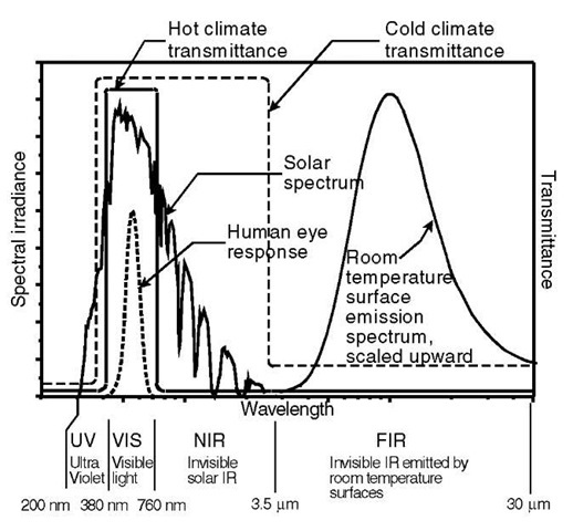
The second kind of coating commonly used in IGUs is a modification of the first. In this case, the purpose is to adapt the coating to the needs of buildings with significant cooling periods—when daytime solar radiant heat gain is as important as (or more so than) conductive heat loss on cold winter nights. In this case, the high spectral reflectance characterizing the FIR region for high solar-gain low-e coatings is extended toward lower-wavelength radiation across the near-IR region to the edge of the visible portion of the spectrum, at which point this reflectivity ideally should drop to zero and permit good transmission of visible daylight, the primary purpose of the window.
This coating is called a low solar gain low-e coating because it reflects near IR solar radiation back outdoors before it can be absorbed in the glazing or transmitted directly to the interior. Invisible solar IR radiation only enters a building as heat and is therefore unwanted in hot climate regions. This relatively new glass coating helps keep a building’s interior cool on hot summer days without placing an unnecessary heat burden on the air cooling system, while still admitting ample quantities of natural daylight. The idealized spectral transmittances of the two types of coatings are illustrated in Fig. 7.
Fig. 7 Spectral irradiances of solar radiation and the infrared emission irradiance from a blackbody at room temperature. The blackbody curve is scaled so that its maximum value is the same as the solar spectrum maximum. Also shown are idealized spectral transmittances of both high and low solar gain low-e coatings.
^W1 Long-wavelength IR Cold-climate low-e coating *Second pane 0pti0nal
^ Solar near IR— Hot-climate solar near IR in principle
- Solar near IR absorber (longwave convertor) reflective coating
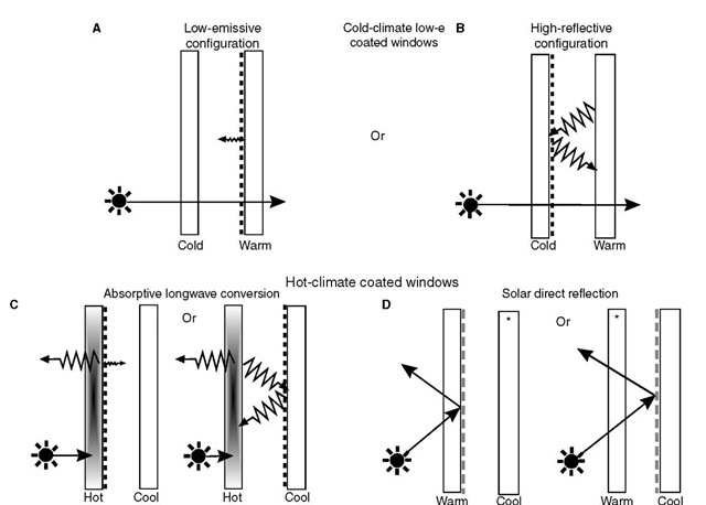
Fig. 8 Coatings and tints for energy efficient glazing systems.
Fig. 8 illustrates several ways these two coatings and spectrally selective absorption in the glass can be used to accomplish energy and illumination objectives in both hot and cold climates.
In Fig. 8, A and B describe the two cold-climate coated window configurations. A has the high-solar-gain low-e coating on surface 3 to reduce the wintertime emission of heat from the warmer inner pane to the colder outer one while B has the coating on surface 2 to reflect the long wavelength IR radiation emitted by the warmer inner pane toward the colder outer one. Likewise, parts C and D illustrate the operation of low-solar-gain low-e coatings in reducing summertime solar heat gain through double pane windows. C illustrates the absorptive case in which solar radiation is absorbed within the outer glass and the emission of the absorbed heat toward the colder inner pane is suppressed by a high solar gain type low-e coating on surface 2 by the low emittance of that coating or it is suppressed by reflection from the low-e coating on surface 3, sending the reflected heat back to the outer pane which dissipates it to the outside air. D illustrates the reflective case in which solar radiation is not absorbed by the glass but rather is reflected from a special low-solar-gain low-e coating on either surface 2 or surface 3, sending that radiation back outdoors, without much of it being absorbed within the window glass. The coating in this case, though reflective to the infrared portion of the solar spectrum, is transmissive over the visible portion, thereby allowing good visible transmittance for good view and daylight admission. In some cases, it is less expensive to increase the chemicals responsible for NIR absorption in glass than to make a low solar gain low-e coating. The high solar gain low-e coating generally has fewer layers and—for this and other reasons—is therefore less expensive to manufacture.
CONDENSATION RESISTANCE
Water vapor generally condenses from the vapor phase to liquid droplets when the temperature of the air or a surface in contact with the air drops below what is known as the dew point temperature, which is the temperature below which water vapor mixed with air at a specific humidity level can no longer remain in the vapor phase. The greater the air’s humidity, the higher the dew point temperature. Condensation on the surfaces of a window is common with insufficiently insulated windows and most often seen when it is cold outside and warm inside. In buildings well-sealed against cold winter air and filled with relatively warm air, the moisture content indoors tends to rise due to several interior sources of water vapor. If a window is not very well-insulated, the window glass and/or frame can lose heat to the cold outside, dropping their interior surface temperatures. When these temperatures drop below the dew point for the indoor air near the window, condensation forms. Condensation can also occur on air conditioned buildings during humid weather conditions, with the condensation in this case forming on the outside surfaces of the window.
Condensation is annoying, impedes the view, and can be destructive to the window and building materials. The solution is to insulate the window better, keeping surfaces adjacent to the humid air warmer than the dew point temperature of that air.
The Condensation Resistance Factor (CRF) is a measure of the effectiveness of a window or glazing system in reducing the potential for condensation. The higher the CRF, the more energy efficient the window and glazing system, generally. Thus, a low U-factor generally leads to a high CRF, as long as there is not a small “thermal short-circuit” in the window system that allows an interior surface to become too cool.
THE “SOLAR HEAT GAIN COEFFICIENT”— SOLAR RADIANT HEAT GAIN
The solar heat gain property of a fenestration is the sum of two factors. See Fig. 5. The first is characterized by the solar transmittance of the window, Ts, given by
where Es^(A) is the solar spectral irradiance distribution and T{A) is the spectral transmittance. The second is the inward-flowing fraction Ni of the window system’s solar absorptance As, given by
where A (A) is the spectral absorptance. Added together, the two of these form what is called the Solar Heat Gain Coefficient (SHGC).
This is the ratio of total solar heat gain through the window to the incident solar irradiance on the window. The solar heat gain Qs through the window is the product of the incident solar irradiance Es over the plane of the window, the area A of the window, and the SHGC value for the window.
VISIBLE TRANSMITTANCE, UV TRANSMITTANCE, AND DAMAGE-WEIGHTED TRANSMITTANCE
The human eye can see only wavelengths over the approximate range from 380 to 760 nm. Radiation outside this range is not visible and should not be called light. The eye’s spectral response follows a bell-shaped curve, seen in Fig. 1 of the entry on daylighting, below the solar spectrum therein plotted, peaking at 555 nm. The visible transmittance Tv of a glazing system is the ratio of luminous flux transmitted by the window to the luminous flux incident upon it, defined by the following equation:
where V(A) is the photopic spectral luminous efficiency function or “V-lambda” weighting function and T(X) is the spectral transmittance of the glazing system. Ty is also known as VT.
The ultraviolet transmittance of a glazing system is also of interest because many people associate the transmission of ultraviolet radiation with fabric fading and other damage to a building’s interior. There have been studies of fading and other damaging effects of solar radiation, but no consensus has yet emerged on which portion of the solar spectrum is most responsible or what spectral weighting function is appropriate for assessing the contribution of different solar UV wavelengths to the damage in a single “UV transmittance” figure. For a while, the straight integrated spectral transmittance from 300 to 380 nm was used, given the symbol T UV. More recently, the spectrum of interest has been extended beyond the UV portion to cover the range from 300 to 700 nm, and a different weighting function was selected. With this system, the V(A) weighting function of Eq. 7 is replaced by another function purported to represent the damaging portions of the solar spectrum. The damage-weighting function is
The resulting damage-weighted transmittance has the symbol T_ dw. The methodology is based on the work of
Jurgen Krochmann in Germany and stems from his studies of the damaging effects of radiation on paintings and other museum artifacts. The Krochmann damage-weighting function was incorporated into ISO/CIE publication 89/3 “On the Deterioration of Exhibited Museum Objects by Optical Radiation” and is referenced by standard NFRC 300 optical properties standard in computing the damage-weighted transmittance T_ dw.[3]
ILLUMINATION
Daylight illumination from windows and other fenestrations can be used to displace electric lighting energy use. The conditions for this to be successful are that: (1) the space should be occupied by people (in need of illumination); (2) the building should be designed for ample, high quality illumination from the fenestration systems; (3) the electric lighting should be turned off or dimmed to save energy when daylighting is adequate; and (4) the sun and sky conditions are such that the daylight illumination incident on the building is adequate. Design for daylighting is discussed in the entry on daylighting.
ENERGY PERFORMANCE
Solar radiant heat gain through windows, which is generally desirable during the winter and undesirable in the summer, and conductive heat transfer are the principal sources of unwanted energy costs associated with fenestrations. They can add to the cost of heating the building in winter and cooling it in summer. Computing the energy costs and savings associated with a building’s fenestration systems has been eased by a variety of computer simulation tools that are now available. The WINDOW program, coupled with THERM for calculating 2-D frame and edge effects, both developed at Lawrence Berkeley National Laboratory, allows rapid calculation of the instantaneous energy performance characteristics of a window.[4] The results of these calculations can be used in computerized hourly building energy performance computer programs. RESFEN is another LBNL computer program for calculating the heating and cooling energy use of windows in residential buildings over a long time period. All of these LBNL computer programs are available for free download at http://windows.lbl.gov/software/. Additional energy simulation tools are available for determining fenestration contributions to a building’s energy performance. They are described at the LBNL web site and some are available there. Additional tools can be found via a Web search.
WINDOW ECONOMICS
Replacing old windows in a building with energy-efficient ones and installing high performance windows during new construction can result in significant yearly energy savings, increased comfort, and improved occupant satisfaction. While these are desirable in residential buildings, better windows can also increase productivity in commercial or office buildings. Occasionally, the productivity enhancements save more dollars than the entire energy bill itself.
Achieving these desirable results can be expensive. (There are exceptions, such as the case where reduced solar heat gain from improved windows allows the air conditioning equipment to be significantly smaller, enough so that the saved equipment costs offset the extra window costs.) In markets driven primarily by least-first-cost goals, it can be difficult to justify the extra costs of better windows. Several accounting tools are available for calculating the longer-term benefits. These include payback time, return on investment, cash flow analysis, life-cycle cost/benefit analysis, and net energy analysis. Using these tools, the designer can capture at least some of the future dollar savings attributable to better windows. But these measures generally fail to include a variety of additional benefits, such as the dollar savings of improved worker productivity, the economic benefits of a healthier society, the values of improved ecosystem health, or the influence of future energy prospects.
CONCLUSION
As we pass the peak of world oil production, entering a subsequent steady decline in oil’s availability, and as we approach future peaks in the production of coal and natural gas, the rising price of fossil fuel energy will shorten payback times and improve other indicators of window economic performance. Government actions, such as green taxes and other positive and negative incentives, can speed the adoption of energy-efficient and otherwise high-performance fenestration systems. Large projects offer higher budgets for design and specification, simplifying decisions to incorporate some of these additional benefits in design and product selection. For smaller projects, perhaps the best advice would be to use the most energy-efficient and affordable window system for comfort and as a hedge against future energy price increases.
