An Interactive Edge Detection Application with MATLAB, Link for Code Composer Studio, and RTDX
Previous embedded DSP applications in this topic either used CCStudio file I/O facilities (accessed via various menu options within the IDE) to feed data to and from the DSP, or image data was hard-coded into an array at compile-time by placing the actual pixel values in C header files. Obviously, both of these methodologies do not lend themselves to enabling any sort of interactive prototyping or proof-of-concept type applications. To that end, TI provides a technology called Real-Time Data Exchange (RTDX)8’9. With RTDX, developers gain continuous and real-time visibility into applications running on the DSP. Data can be transferred from applications running on a host PC down to an embedded target DSP, and vice-versa.
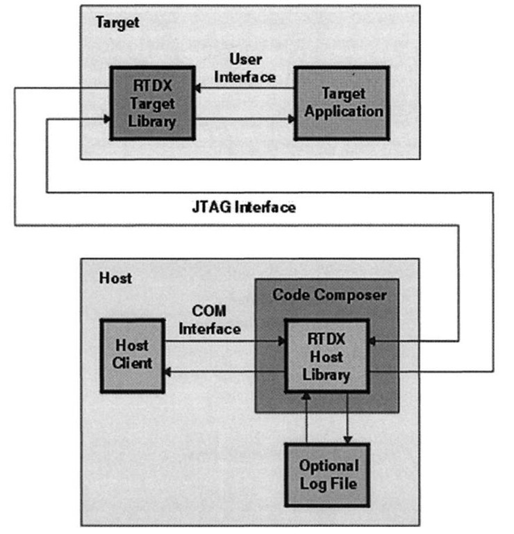
Figure 5-7 illustrates just how RTDX fits into the loop. In our application, the host client is a MATLAB application that hooks up to CCStudio, also running on the host. CCStudio in turn links up with the target, where the DSP is executing a program. This figure brings out a key point with respect to RTDX, namely that the CCStudio application must be running on the host in order for RTDX to function.Also note that RTDX data transfer pipes are half-duplex in that they are unidirectional in nature. Two-way (or full-duplex) data transfer can be implemented using two separate RTDX pipes and configuring them appropriately.
Figure 5-7 also shows a Component Object Model (COM) interface between the host client application and CCStudio. COM is a Microsoft Windows technology for building applications from binary software components enabling a "plug-in" architecture. It is COM that serves as the underpinnings of the Internet Explorer (IE) web browser, so that various software vendors can develop components that seamlessly integrate into the browser. As such, utilizing COM on the host for RTDX is a natural choice as it enables developers to use RTDX services from within a myriad of contexts: custom C/C++ applications (a route taken in 5.2.5.2), Visual Basic, or even Excel (by using Visual Basic for Application, or VBA, to bring data in from an RTDX pipe into an Excel worksheet). In this case the host client application takes the form of a MATLAB program, but how does MATLAB initiate the connection to RTDX over COM?
Figure 5-7. Interplay between RTDX and various components on the host and target devices. Figure reprinted courtesy of Texas Instruments.
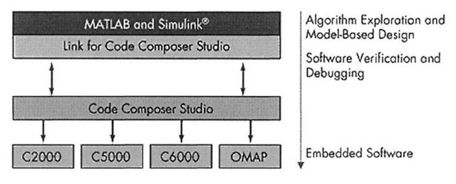
Figure 5-8. Using Link for Code Composer Studio to communicate with an embedded DSP target from within MATLAB. The Link for Code Composer Studio Development Tools includes a set of functions and structures that call upon various TI host utility libraries to shuttle data between CCStudio and MATLAB. Figure reprinted courtesy of The MathWorks.
MATLAB offers built-in support so that it can act as a COM client, or alternatively one could develop a MEX-file in C/C++ that uses the TI RTDX COM object directly and provides a MATLAB interface to it. However, The MathWorks has already developed the Link for Code Composer Studio10 to facilitate precisely this sort of communication with a TI DSP development platform, and which encapsulates the TI COM object in a fashion amenable to MATLAB developers. Figure 5-8 shows where this toolbox resides within the hierarchy of a host-target MATLAB application.
This product provides a suite of MATLAB functions for communicating with CCStudio, transferring information back and forth via RTDX, and extracting information about data and functions residing on the target. The product is at the core of the host application presented in this section, for without it communication between the host and target becomes a painful process. Unfortunately we will get a feel for this pain in 5.2.5.2 when we implement a subset of this functionality, without the services of MATLAB in a C/C++ Visual Studio application. While it is theoretically possible to implement a MEX-file that provides a MATLAB wrapper around the TI COM objects, implementing and debugging such a beast is not for the faint of heart. In addition to the RTDX communication functionality featured here, the Link for Code Composer Studio also provides a wealth of additional tools for instrumenting DSP code and running hardware-in-the-loop or processor-in-the-loop simulations.
The Sobel edge detection application featured in this section consists of two parts, the MATLAB front-end host that provides user input and data visualization, and the DSP back-end target that runs the image processing algorithm. The MATLAB GUI front-end looks the same as its stand-alone predecessor and its implementation can be found on the CD-ROM in the directory Chap5\edge\SobelFixedRTDX\Host. Two target DSP projects are provided, one for the C6416 DSK and another for the C6701 EVM. While the code for the MATLAB host remains the same no matter which target is used (except for the code that loads the target project), the implementation for each of the two targets differs slightly.
To run the application one first needs to modify the MATLAB host (Chap5 \ edge \SobelFixedRTDX\Host\ Sobel Demo .m) to point to the location of the desired target COFF executable file. Starting the GUI by issuing the command SobelDemo initializes the DSP by invoking the CCStudio IDE, connecting to it, loading the project file and associated binary executable, and finally running the program on the DSP. All of this is accomplished using various commands provided by the Link for Code Composer Studio. If the CCStudio IDE is already running, there is no need to close it down prior to starting SobelDemo, simply ignore any warnings that appear in the MATLAB command window. After initialization, from the point-of-view of the end-user, the entire application operates in the same manner as before. Of course, the major internal difference is that a DSP is doing the processing instead of sobel_edge_detect_fixed.m. The embedded DSP program meanwhile sits in a continual loop, eagerly awaiting image data from the host PC. When it receives a threshold and image via RTDX, the program proceeds to use IMGLIB functions to locate the edges in the image.
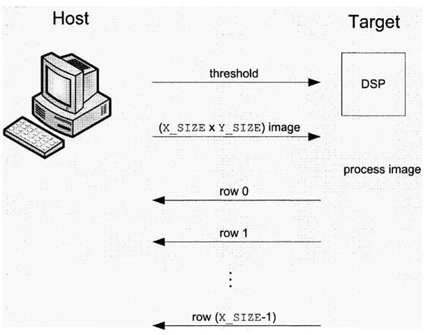
The protocol between the host and target is shown in Figure 5-9. The receipt of a single integer value (the threshold) is a signal to the target that it should expect the image data to immediately follow. After this data is received and the image processed, the target sends the processed pixels back to the host. As shown in Figure 5-9, the manner in which data is sent from the host and is received from the target differs. From the target’s vantage point, reading large blocks of data is less problematic than writing blocks data. An entire image can be sent from the host to the target in one fell swoop, but unfortunately that is not the case in the opposite direction. In fact, the processed image has to be sent one row at a time, and for the C6701 EVM a pause in the writing must be inserted to give the host a chance to catch its breath, so to speak.
Figure 5-9. Data flow protocol between the Sobel edge detection host and embedded DSP target doing the actual image processing.
This particular data transfer protocol assumes a fixed image size, because the image dimensions are never transferred between the host and target. In this application, the image dimensions are X_SIZE (rows) and Y_SIZE (columns), both of which are set to 256 by default in the image . h header file. As a consequence, the host uses the imresize Image Processing Toolbox function to resize the input image to be of dimensions 256×256, prior to sending it to the target11.
DSP/BIOS
Until this point, all CCStudio projects have been fairly bare-bones, eschewing a formal operating system, using manually crafted linker command (. cmd) files, and configuring peripherals manually through the CSL API (e.g., DMA and EDMA in 4.3.4). The CCStudio RTDX tutorial and sample projects suggest it is possible to continue along this route -however it is the author’s experience that when used in the context of transferring large amounts of data, RTDX works far more reliably when used in conjunction with the TI real-time operating system, DSP/BIOS12. In fact, some of the very simple C6701 EVM tutorial samples do not work at all without recreating them to incorporate DSP/BIOS. DSP/BIOS is a fully preemptive real-time operating system (RTOS), featuring:
• Real-time scheduling based on a preemptive thread management kernel.
• Real-time I/O facilities, like RTDX, that engender two-way communication between different threads or tasks running on the target, or between the target and host PC.
• Real-time analysis tools, such as Software Logic Analyzer, Message Log, CPU Load Graph and Real-Time Profiler.
The DSP/BIOS Real-Time OS is scalable, meaning that the developer has the ability to reduce its overall footprint by using only what is required for a particular application. This type of scalability is enormously important in embedded systems where resources come at a premium. DSP/BIOS is configured using a graphical interface from within CCStudio, and the steps to add DSP/BIOS support to an existing or new project are enumerated below:
1. Select File|New|DSP/BIOS Configuration, and choose the appropriate base seed (e.g. C6701.cdb for the C6701 EVM or C 64xx. cdb/ds k6416 . cdb for the C6416 DSK).
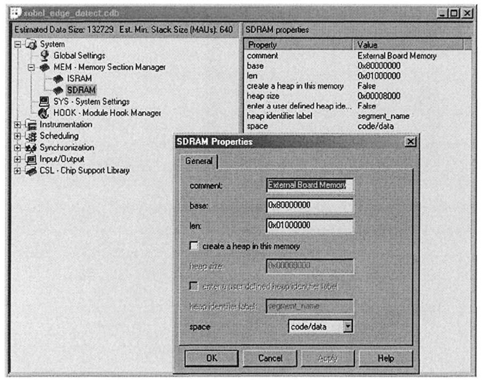
2. One normally then proceeds to configure the chip’s memory map (which we have previously done using linker command files), although this is not necessary if external RAM is not going to be utilized. We do this by adding one or more memory blocks that point to external RAM. The "System" DSP/BIOS configuration tree contains four items: the Memory Section Manager, Buffer Pool Manager, System Settings, and Module Hook Manager. After expanding the System tree, right-clicking on the Memory Section Manager shows an option to insert a "MEM" module. Right-clicking on this new module allows one to rename it and also set its properties, which should normally mirror what goes into the linker command file. For example, in the case of the C6416 DSK, one would add a 16 MB segment conforming to the addresses specified in [13], as shown in Figure 5-10. The base address and length may be garnered from working linker command files. Data buffers can now be mapped in the source code to this segment using the familiar DATA_SECTION pragma, where the identifier specified in the pragma declaration would refer to the name specified in the DSP/BIOS MEM configuration. If 6416ds k. cdb was chosen as the base seed configuration, then this step is not required as the DSP/BIOS configuration already includes an SDRAM MEM module.
3. After the memory configuration has been set, save the DSP/BIOS configuration to a . cdb file, and then add this file to the CCStudio project.
4. The act of saving the DSP/BIOS configuration in step 3 also results in the creation of a linker command file, which should never be hand-modified by the user, as any such changes will be overwritten by the DSP/BIOS configuration tool should the configuration change in the future. Anything that can be done by manually altering the linker command file can be accomplished in one form or another through the DSP/BIOS configuration tool. The newly generated linker command file must also be added to the project.
There is no longer any need to explicitly link to the runtime-support library (rts6400.1ib for the C6416 DSK or rts6701.1ib for the C6701 EVM) for DSP/BIOS projects. In addition, it is no longer required to call DSK6416_init (for C6416 DSK projects) or evm_init for C6x EVM projects), as the OS now takes care of properly initializing the development board.
Figure 5-10. Using the DSP/BIOS configuration utility to set up the memory map for the C6416 DSK. In this example the SDRAM external memory section is configured.
C6416 DSK Target
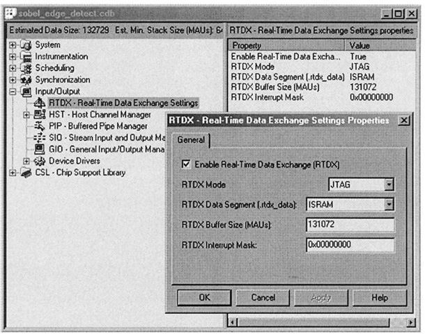
The C6416 DSK Sobel project is located in the Chap5\edge\SobelFixedRTDX\ Target\C6416DSK directory. In general, RTDX works more reliably on this development platform, as compared to the C6701 EVM. Prior to using RTDX in a project, it must be correctly configured, with one of the main settings being the maximum size of the buffers used internally by the RTDX system. The online tutorial states that to change the buffer size a copy of the rtdx_buf. c file should be modified and explicitly linked into the project. When using DSP/BIOS, this inconvenience is avoided and the DSP/BIOS configuration tool should be used instead. There is a separate RTDX section from within DSP/BIOS, under the "Input/Output" tree. Expanding this tree, and right-clicking on the RTDX icon, exposes a dialog where various RTDX settings are made. This dialog is shown in Figure 5-11.
Figure 5-11. Configuring RTDX for the C6416 DSK target project, using the DSP/BIOS configuration tool.
Since this project defines both X_SIZE and Y_SIZE as 256, and the pixels are stored in an 8 bpp format, the RTDX buffer size should really only need to be 65536 (64K) bytes; however, given the vagaries of RTDX, the bigger the better, so long as the buffer can be stored in internal on-chip RAM (for performance reasons). Experiments show that doubling the RTDX buffer size increases overall system reliability, hence for the C6416 target the buffer size is set to 128K, which still fits into the C6416′s internal chip RAM because of that processor’s expanded memory (as compared to the older C62x and C67x DSPs).
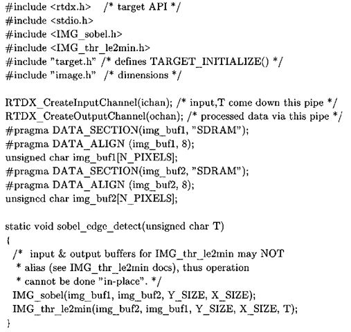
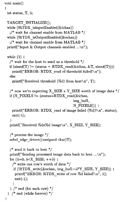
For the sake of simplicity, this project, as well as its close C6701 cousin, does not utilize the paging and DMA optimizations described in 4.3.5 and 4.4.2, and all image buffers are placed in external RAM. Listing 5-3 is the full contents of the C6416 target source file sobel_edge_detect. c, which implements the protocol described in Figure 5-9 and of course the Sobel edge detection image processing functionality.
Listing 5-3: sobel edge detect, c
This program sits in a continual loop, waiting for data to jump-start the processing. The receipt of a single integer value, containing the threshold used during segmentation of the edge enhanced image, is a signal to the target that the host will be sending down pixel data for processing. The blocking function (meaning it does not return until the operation has completed) RTDX_read is used to read data from an RTDX "channel", or pipe. There is a non-blocking version of RTDX_read, called RTDX_readNB which returns immediately. When using this function, it is then the responsibility of the application to poll RTDX via the RTDX channelBusy macro to wait for the read operation to complete. In this fashion, the DSP would be free to perform other useful work while the RTDX system does the grunt work of transferring data to or from the host.
After receiving the threshold value from the host, the target reads the entire image in one fell swoop with another call to RTDX read. Once this invocation of RTDX_read returns, the target has all the data it needs to process the image. The actual image processing occurs within sobel_edge_detect, where the image is passed through 3×3 Sobel vertical and horizontal kernels using the IMGLIB function IMG_sobel and the edge enhanced image is formed by combining the intermediate results using the absolute value approximation to the gradient. IMG_sobel is implemented in such a manner that the first and last columns of the output are invalid, and the output is two rows shorter than the input. This implementation detail is utilized by the host application, which zeros out those portions of the returned image prior to display.
Once the gradient image is available, the actual edge detection is carried out by thresholding the gradient image using another IMGLIB function, IMG_thr_le2min. This function is similar to the MATLAB Image Processing Toolbox function im2bw14, except that it zeros out those pixels that lie below a given threshold – the remaining pixels are left unmodified, whereas with im2bw all non-zero pixels are set to 1. IMGLIB provides four variants of the basic threshold operation (IMG_thr_gt2max, IMG_thr_gt2thr, IMG_thr_le2min, IMG_thr_le2thr) that allow one to set pixels above or below a given threshold value to either an extreme value (0 or 255) or a specified intensity. All four of these IMGLIB thresholding functions leave the pixels that do not meet the threshold criterion untouched, which has ramifications on our host application because it displays the processed output as a binary image.
A significant difference between this code and previous TI implementations in this topic is in that the input image buffer is actually overwritten during the image processing. As is evident from a close inspection of sobel_edge_detect, the output of IMG_sobel is placed into img_buf2; img_buf2 is then the input to IMG_thr_le2min, which outputs the thresholded image back into img_buf 1. The reason for this is that IMG_thr_le2min, for performance reasons, dictates that its two input buffers not alias – that is, point to the same memory location. One way of circumventing this restriction would be to use three image buffers, which of course comes at the cost of a larger memory footprint. Yet if this edge detection were part of a larger system requiring access to the original pixel data further downstream the processing chain, then such a strategy would have to be used.
After the edge detection runs its course, all that remains is to send the pixel data back to the host. In contrast to reading image data from an RTDX input channel, writing the same amount of data in a single block is more problematic. Using a single RTDX call to write the processed data to the output channel in a single contiguous block should look like RTDX_write (Sochan, out_img, N_PIXELS) . Unfortunately, that function call does not work as advertised. In fact, splitting the target-to-host image transfer into two operations (sending the first half, followed by the second half) also fails to work reliably. It was found that the most robust and reliable means of performing the data transfer is to send the data on a row-by-row basis, which is the reason for the final loop in sobel_edge_detect.c.
