7.4
Pumps are the largest user of electric motors in the integral-horsepower sizes 1 hp and larger. The selection and application of electric motors and adjustable-speed systems to pumps become very complex and difficult because of the large numbers of types of pumps and their lack of standardization. The pumps fall into two broad categories: displacement pumps and dynamic pumps. The dynamic pumps include noncentrifugal and centrifugal types. The highest percentage of the pumps used for industrial processes are of the centrifugal type; therefore, the discussion in this section will be limited to drive applications of this type.
In the selection of a pump for a given system, the system characteristics must be determined in terms of flow rate in gallons per minute versus total head, in feet, under all flow rates expected. The system should include an allowance for pipe corrosion and other factors that affect the system characteristics. The pump then selected should be sized to the system characteristic at the maximum flow rate such that the efficiency is close to the optimum for the pump. Then, for an adjustable-speed system, it is necessary to check the pump performance at the minimum flow point required.
The various pump manufacturers provide data for their pumps and also provide assistance in selecting the correct pump for the
TABLE 7.3 Net Present Worth Comparison in Dollars for Adjustable-Flow Fan Systems3
| System | ||||||
| Fluid drive or | Variable- | Wound-rotor | ||||
| Operating | Multi speed | Variable | eddy current | Mechanical | frequency | motor with rotor |
| cycle | motor | vane inlet | drive | vari drive | system | loss recovery |
| I | — | 3,558 | 5,143 | 1,388 | 4,271 | 10,176 |
| II | — | 17,571 | 24,528 | 27,746 | 29,973 | 35,029 |
| I [ 1 | — | 27,416 | 40,569 | 48,381 | 50,551 | 53,831 |
| I-A | 13,727 | — | — | — | ■ ■ | — |
| III-A | 44,018 | — | — | — | — | — |
| a Base for comparison: damper control. | ||||||
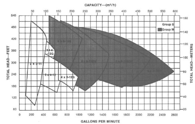
application. The initial guide is a performance curve at a fixed speed, as shown in Fig. 7.57, indicating the best efficiency point on each pump in a family of pumps. For a given pump, detail performance curves such as those in Fig. 7.58 are available from the manufacturer.
The following relationship applies to pumps (as discussed for fans in Sec. 7.3):
1780 R.P.11. Performance Curve
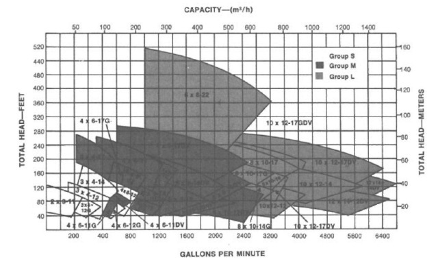
FIGURE 7.57 3550- and 1780-rpm centrifugal pump performance curves. (Courtesy Gould’s Pumps Inc., Seneca Falls, NY.)
![tmp30-15_thumb[1] tmp30-15_thumb[1]](http://lh5.ggpht.com/_X6JnoL0U4BY/S1gdvxlBCeI/AAAAAAAAHnI/EhY8QLCVe1U/tmp3015_thumb12.jpg?imgmax=800)
![tmp30-16_thumb[1] tmp30-16_thumb[1]](http://lh5.ggpht.com/_X6JnoL0U4BY/S1gd1VxPvCI/AAAAAAAAHnQ/E1Ju-XqAFbs/tmp3016_thumb1_thumb.jpg?imgmax=800)
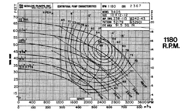
FIGURE 7.58 Centrifugal pump performance at the selected speeds 1780 and 1180 rpm. (Courtesy Gould’s Pumps Inc., Seneca Falls, NY.)
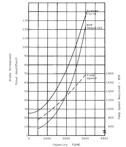
FIGURE 7.59 Sample fluid system characteristic.
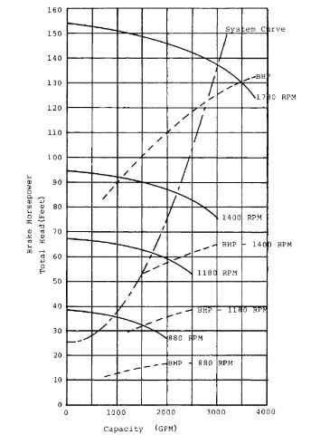
FIGURE 7.60 Centrifugal pump characteristics.
TABLE 7.4 Summary of Sample Calculations for Adjustable-Flow Systems
| Flow | Pump” BIIP required |
Throttling system | Eddy current drive or fluid drive | AC variable -frequency system | Wound-rotor motor with slip loss recovery | ||||
| rate, Flow, % gpm | Input, kW | Losses, kW | Input, kW | Losses, kW | Input, kW | Losses, kW | Input, kW | Losses, kW | |
| 100 3000 75 2250 50 1500 | 125 60 28 | 100,81 92.65 80.56 | 7.56 47.89 59.67 | 107.26 61.29 36.89 | 14.0 16.5 16,0 | 103.96 51.15 24.60 | 10,71 6.39 3,72 | 101.91 51.45 25.17 | 8.66 6.69 4.28 |
| a For adjustable-speed pump. | |||||||||
Figure 7.59 shows the system flow characteristic and the centrifugal pump characteristics at various pump speeds for the specific application. Figure 7.60 shows the pump characteristic at various speeds and the system characteristics as a function of flow requirements.
The pump BHP, the power input, and the power losses from the power line to the pump can be calculated for each method of flow control. A summary of these calculations is shown in Table 7.4 for three flow conditions: full flow (100%), 75% flow, and 50% flow.
The annual power savings and present net worth of the savings for each system can be determined for a specific set of conditions. To continue the sample calculations, set the following conditions:
Annual operating hours, 8000 hr Operating cycle:
full flow, 50% of the time 75% flow, 30% of the time 50% flow, 20% of the time
Full-flow BHP, 125 hp Initial power rate, $0.06/kWh Annual increase in power rates, 15% Cost of money, 20% Tax rate, 40%
TABLE 7.5 Annual Energy Savings and Net Present Worth for Adjustable-Speed Pumping Systemsa
| Annual | Net present | |
| System | savings, kWh | worth, $ |
| Fluid drive or | 120,056 | 30,907 |
| eddy current system | ||
| AC variable-frequency | 179,536 | 45,448 |
| system | ||
| Wound rotor with slip | 183,104 | 47,141 |
| recovery system | ||
| a Base for comparison: throttling system. | ||
The summary of these calculations in Table 7.5 shows the savings that can be achieved by means of adjustable-speed pumping systems compared to a throttling-type system. These calculations indicate that substantial power savings can be achieved with variable-speed types of pumping systems. The selection of the most effective system depends on the comparison of the system cost to the net present worth of the system savings and on application factors such as environment and maintenance.
