7.3
Various types of fans used to move air or other gases are among the largest consumers of electric power and among the largest users of integral-horsepower electric motors. In general, fans can be divided into two broad categories: centrifugal fans and axial flow fans.

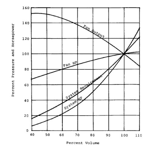
FIGURE 7.52 Sample application, characteristic fan data, and system characteristic.
The guide for selection of the proper fan for a given application is covered by most fan manufacturer catalog information. However, to obtain the most energy-efficient system, it is necessary to examine the methods of controlling airflow in a given system.
First, it is necessary to determine the system resistance characteristic for various airflow rates. A curve can be developed for the system in terms of the air volume versus the static pressure required. This curve generally follows a simple parabolic law in which the static pressure or resistance to airflow varies as the square of the volume of air required. Figure 7.52 shows the system curve for a specific example that will be discussed later.
Next is the selection of the type of fan. Many of the applications in general heating, ventilating, and air conditioning systems involve centrifugal fans. These fans generally fall into three major categories based on the type of impeller design:
1. Backward-curved blades.
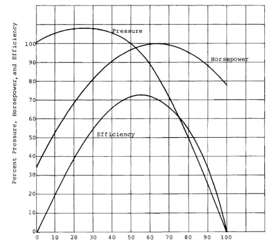
The horsepower reaches a maximum near peak efficiency and becomes lower toward free delivery. Figure 7.53 is the typical performance curve for the backward-curved fan. The volume is the percent of free-flow volume, and the pressure is the percent of static pressure at zero volume. The horsepower is the percent of maximum horsepower.
2. Radial blades.
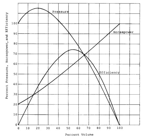
These have higher-pressure characteristics than the backward-curved fan. The horsepower rises continually to free delivery. Figure 7.54 is the typical performance curve for radial-blade fans.
3. Forward-curved blades.
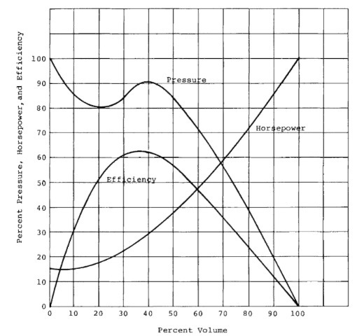
The pressure curve is less steep than that for the backward-curved fan. The peak efficiency is to the right of the peak pressure. The horsepower rises continually to free delivery. Figure 7.55 is the typical performance curve for forward-curved fans.
The size and type of fan selected should be such that the fan is operating near its peak static efficiency for the maximum flow rate required. The performance of the fan at other speeds will follow the following fan laws:

FIGURE 7.53 Characteristic curves for the backward-curved fan.
1. The volume V of air varies as the fan speed.
2. The static pressure P varies as the square of the fan speed.
3. The horsepower varies as the cube of the fan speed.
![tmp30-8_thumb[2] tmp30-8_thumb[2]](http://lh5.ggpht.com/_X6JnoL0U4BY/S1gdR55191I/AAAAAAAAHmU/uH3eFbTE5Nw/tmp308_thumb2_thumb.jpg?imgmax=800)

FIGURE 7.54 Characteristic curves for the radial fan.
Several methods of controlling the airflow can be considered:
Damper control
Variable inlet vane control
Hydrokinetic or fluid-drive systems
Eddy current drive systems
Mechanical variable-speed drive units
AC variable-frequency systems
Wound-rotor motor with slip recovery systems
Two-winding, two-speed motors

FIGURE 7.55 Characteristic curves for the forward-curved fan.
Based on this fan-system curve, the horsepower input at the fan to produce the airflow is also shown. Figure 7.56 shows the input horsepower required for each of the preceding systems compared to the fan horsepower required as the airflow requirement is varied between 40 and 100% volume.
To determine the most energy-efficient system, the operating cycle, i.e., the percent time operating at each volume flow, must be determined; then the energy savings and net present worth of each system can be compared to the most inefficient system, i.e., one using a discharge damper.
To illustrate these data, three different operating cycles have been assumed with the following data:
Horsepower at full air volume, 100 hp Annual operating hours, 4000 hr Initial power rate, $0.06/kWh Annual increase in power rate, 10% Cost of money, 15%
Tax rate, 40%
System life, 10 yr The operating cycles are as follows:
| Cycle | Time at each air volume, % | ||
| 100% air | vol. 80% air vol. | 60% air vol. | |
| I | 75 | 15 | 10 |
| TT | 33 | 33 | 34 |
| in | 10 | 15 | 75 |
Two other operating cycles based on fixed-speed operation at two speeds using a two-winding, two-speed motor with an 1800/ 1200-rpm speed combination are as follows:
Operating cycle 1-A:
100% (full) air volume: 75% of the time
66% air volume: 25% of the time
![tmp30-11_thumb[1] tmp30-11_thumb[1]](http://lh3.ggpht.com/_X6JnoL0U4BY/S1gdiHPKBCI/AAAAAAAAHms/epT_m8U9Qvo/tmp3011_thumb1_thumb.jpg?imgmax=800)
FIGURE 7.56 Power input for adjustable-flow systems: (1) fan horsepower required, (2) damper control, (3) inlet vane control, (4) hydrokinetic and eddy current system, (5) mechanical varispeed system, (6) variable-frequency system, (7) wound rotor with rotor loss recovery system; 100% power is the power input to the motor at 100% airflow.
TABLE 7.2 Comparison of Annual Kilowatt-Hour Savings for Adjustable Flow Fan Systems3
| Syste; | m | |||||
| Fluid drive or | Variable- | Wound rotor | ||||
| Operating | Multi speed | Variable | eddy current | Mechanical | frequency | with |
| cycle | motor | vane inlet | drive | van.clri.VL’ | system | slip recovery |
| I | — | 10,431 | 15,080 | 4,070 | 12,550 | 32,768 |
| TT | — | 51,515 | 71,916 | 81,355 | 87,879 | 103,008 |
| 111 | — | 80,382 | 118,948 | 141354 | 148,216 | 157,834 |
| I-A | 39,396 | — | — | — | — | — |
| III-A | 129,060 | — | — | — | — | — |
| a Base for comparison: damper control. | ||||||
Operating cycle 1-B:
100% (full) air volume: 25% of the time
66% air volume: 75% of the time
The summary of the annual power savings in kilowatt-hours for each system is shown in Table 7.2. The net present worth of the energy savings based on the defined assumptions is shown in Table 7.3. This summary shows the influence of the operating cycle on the power savings and the net present worth of those savings. When compared to the first cost of each system in conjunction with other considerations, including reliability, flexibility, maintenance, and environment, this net present worth will provide an economic basis for selecting the most cost-effective system.
