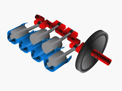
Crankshaft Working
Power from the burnt gases in the combustion chamber is delivered to the crankshaft through the piston,piston pin and connecting rod.The crankshaft (fig.3.62) changes reciprocating motion of the piston in cylinder to the rotary motion of the flywheel.Conversion of motion is executed by use of the offset in the crankshaft.Each offset part of the crankshaft has a bearing surface known as a crank pin to which the connecting rod is attached.Crank-through is the offset from the crankshaft centre line. The stroke of the piston is controlled by the throw of the crankshaft. The combustion force is transferred to the crank-throw after the crankshaft has moved past top dead centre to produce turning effort or torque, which rotates the crankshaft. Thus all the engine power is delivered through the crankshaft. The cam-shaft is rotated by the crankshaft through gears using chain driven or belt driven sprockets. The cam-shaft drive is timed for opening of the valves in relation to the piston position. The crankshaft rotates in main bearings, which are split in half for assembly around the crankshaft main bearing journals.
Both the crankshaft and camshaft must be capable of withstanding the intermittent variable loads impressed on them. During transfer of torque to the output shaft, the force deflects the crankshaft. This deflection occurs due to bending and twisting of the crankshaft. Crankshaft deflections are directly related to engine roughness. When deflections of the crankshaft occur at same vibrational or resonant frequency as another engine part, the parts vibrate together. These vibrations may reach the audible level producing a “thumping” sound. The part may fail if this type of vibration is allowed to continue. Harmful resonant frequencies of the crankshaft are damped using a torsional vibration damper. Torsional stiffness is one of the most important crankshaft design requirements. This can be achieved by using material with the correct physical properties and by minimizing stress concentration.
The crankshaft is located in the crankcase and is supported by main bearings. Figure 3.62 represents schematic view of a typical crankshaft. The angle of the crankshaft throws in relation to each other is selected to provide a smooth power output. V-8 engines use 90 degree and 6 cylinder engines use 120 degree crank throws. The engine firing order is determined from the angles selected. A crankshaft for a four cylinder engine is referred to a five bearing shaft. This means that the shaft has five main bearings, one on each side of every big end which makes the crankshaft very stiff and supports it well. As a result the engine is normally very smooth and long lasting.
Crankshaft.
This Figure describes that how a crankshaft is fitted in a car.Its joining from Cylinders to piston to crankshaft to itself and then to the wheels of the car.
Because of the additional internal webs required to support the main bearings, the crank case itself is very stiff. The disadvantages of this type of bearing arrangement are that it is more expensive and engine may have to be slightly longer to accommodate the extra main bearings. Counter weights are used to balance static and dynamic forces that occur during engine operation. Main and rod bearing journal overlap increases crankshaft strength because more of the load is carried through the overlap area rather than through the fillet and crankshaft web. Since the stress concentration takes place at oil holes drilled through the crankshaft journals, these are usually located where the crankshaft loads and stresses are minimal. Lightening holes in the crank throws do not reduce their strength if the hole size is less than half of the bearing journal diameter, rather these holes often increase crankshaft strength by relieving some of the crankshaft’s natural stress. Automatic transmission pressure and clutch release forces tend to push the crankshaft towards the front of the engine. Thrust bearings in the engine support this thrust load as well maintain the crankshaft position. Thrust bearings may be located on any one of the main bearing journals. Experience shows that the bearing lasts much longer when the journal is polished against the direction of normal rotation than if polished in the direction of normal rotation. Most crankshaft balancing is done during manufacture by drilling holes in the counterweight to lighten them. Sometimes these holes are drilled after the crankshaft is installed in the engine.


