15.11.
Starter-motor Maintenance and Fault Diagnosis
The most important component of a starting system is the battery, and until this is in sound condition, the speed of starter motor remains low and possibly with a limited duration of cranking. However, a battery may be faulty due to other factors like, a defective charging system, a short to earth in another system, or overload of the battery due to driving or seasonal conditions. Indications from warning instruments and observation of the engine’s starting performance, enable the driver to identify the initial conditions that may lead a major fault.
A battery supplies a very large current to the starting motor, and hence a drop in the battery p.d. takes place. When this drop is very high, the ignition system does not receive sufficient power to provide suitable spark at the plugs, although the starting motor is still functioning at a low speed. This condition is confirmed when an engine fails to start with the motor, but starts easily by “bump starting” (rolling the vehicle in top gear and suddenly releasing the clutch). Normally this problem is attributed to a battery fault, but on many modern engines the problem is resolved by installing cold-start ballast resistor in the ignition supply lead. In addition to the resistor lead, a separate lead is used between a terminal on the starter solenoid and the ignition coil so that the resistor is bypassed when the starter is operated.
Maintenance.
Routine maintenance work should be attended to the battery, especially the terminals. All terminals and connectors in the starter circuit should be maintained clean and secure.
Fault Diagnosis.
If the probable defects of each component of the system are considered, along with the possible symptoms indicated by each defect, then it is possible for the electrician to find a likely cause of a particular fault. The main problems, and the possible faults, faced by various components of the starting system, are presented below.
| Battery : | Low state of charge or defective. |
| Terminals | High resistance due to corrosion or slackness. |
| Cables : | Broken or partially broken, especially the earth-bonding strap |
| between the engine and frame. | |
| Solenoid : | Dirty contacts or faulty connection between windings and |
| terminals. | |
| Starter switch : | High resistance at contacts or broken cables. |
| Motor | Poor bedding of brushes or dirty commutator. |
| Pinion : | Not meshing or jammed due to a worm flywheel ring gear. |
Table 15.1 presents various faults and their possible causes.
The second column indicates some initial checks that help in the diagnosis of the actual cause. Identification of the precise cause often requires the use of test equipment. If a starting motor during operation seizes the engine, then it indicates that the teeth on the flywheel have worn sufficiently so that the gears jam together as they attempt to mesh.
Table 15.1. Fault Diagnosis. |
||
| Symptom | Result of initial check | Possible cause |
| Low cranking speed | Lights dim when starter switch is operated. | Discharged or defective battery. Poor connections between battery and solenoid. High resistance of engine. |
| Starter does not operate | No lights or lights go out when starter is operated. | Discharged or defective battery, Poor connection between battery and solenoid or between battery and earth. Severe short circuit to earth in starting motor. |
| Solenoid ‘clicks’ when starter switch is operated, but lights are unaffected. | Poor connection between solenoid and motor. Broken or insecure earth strap. Defective solenoid. Defective motor, most probably commutator or brushes. |
|
| No ‘click’ from solenoid ; but lights remain unaffected. | Defective solenoid. Defective starter switch. Poor connections between starter switch and solenoid. Defective inhibitor (auto transmission). |
|
| Repeating ‘clicking’ from solenoid; but lights unaffected. | Borken holding coil in solenoid. | |
| Repeated ‘clicking’ from solenoid ; but lights dim. | Discharged or defective battery. | |
| Lights dim when starter is operated and engine has seized. | Pinion tenth jammed in flywheel. Engine has seized due to engine problem. | |
| Starter ‘whines’ but pinion does not engage | Dirt on helix (inertia drive). Defective pinion engagement system (pre-engaged). |
An engine always comes to rest at the start of one of the compression strokes, so the flywheel becomes burred due to pinion entry in these positions. The number of places where wear occurs around the circumference of the flywheel depends on the number of cylinders of the engine e.g. 2 places for 4-cylinder engine, 3 places for 6-cylinder engine, and 4 places for 8-cylinder engine.
A spanner was used in the past to wind-out the pinion after it had jammed, but today on a modern unit it is necessary to slacken-off the securing bolts of the motor. In emergency, a pinion is made free by rocking the car backwards and forwards with top gear engaged and the ignition off, but this practice may cause a bent armature spindle.
Most starter-ring gears are held in position by a interference fit with the flywheel. For fitting a new gear, the worn gear is removed by drilling a hole in the gear and then splitting the ring with a chisel. The new ring is preheated to the recommended temperature and, while hot, it is tapped into place ensuring that the chamfer on the teeth is positioned on the side of pinion entry.
Circuit Tests.
Before initiating these tests, the battery should be checked by using a hydrometer and heavy-discharge tester for its sound condition. A moving coil is used to conduct the voltmeter (0-20 V range) tests shown in Fig. 15.35 and all readings are observed when the engine is being cranked. The low-tension ignition circuit should be disconnected to prevent the engine starting, or, in the
case of a diesel engine, the stop control should be operated. Although the diagram shows an inertia drive motor, the same method is also used on a pre-engaged motor.
Test 1 - The meter is connected across the battery and the reading is noted. If the voltage is less than 10 V the battery is suspected.
Test 2, 3, 4 - Readings observed at these points should be similar to test 1. If the reading at point 4 indicates a voltage drop greater than 0.5 V, then the cause of the resistance should be investigated.
Test 5 - This test determines the voltage drop on the earth side of the circuit. If the reading is greater than 0.25 V then all earth connections should be checked, especially the engine-bonding strap.

Fig. 15.35. Starting motor circuit tests.

Fig. 15.36. Volt drop test to locate resistance.
A high resistance at any joint causes drop in voltage. This can be checked with the help of a voltmeter connecting across the part of the circuit where the resistance is suspected (Fig. 15.36). When the voltage applied to the starter is lower than specified, the current reduces causing a low motor’s speed and torque of the motor.
Brushes and Commutator.
If the motor fails to operate, when the battery and external circuit are all right, then the motor should be removed, dismantled and inspected. The earth terminal of the battery must be disconnected before initiating removal of the motor.
Commutator.
Commutator should be cleaned with a petrol-moistened cloth. Any burnt spots can be removed by using fine glass paper, but not with energy-cloth. If a satisfactory surface is not obtained, then it is necessary to skim the commutator in a lathe.
Brush Gear.
All brushes must move freely in their boxes, the springs must exert sufficient force and each brush should not be less than the specified length. In the Lucas motors, the minimum length of brush is 9.5 mm and 8 mm for face type and cylindrical commutators respectively.
When a new brush is fitted the brush lead is soldered to the appropriate connector point. In the case of aluminium-alloy field coils, the cold brush lead is cut at a given distance from the field and the new lead is soldered to the old lead. A brush used on a cylindrical commutator must be bedded-in to the same contour as the commutator using glass paper.
Bench Testing the Motor.
The following three tests are applied to the motor.
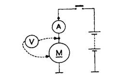
Light-running Test. On a test stand the power of the motor can be measured (Fig. 15.37) under free running conditions. The test must be conducted in a short time, because the centrifugal effect at the no load speed can cause damage to the armature windings. A Lucas 9M90 motor normally draws 840 W from a 12 V supply.

Fig. 15.37. Position of meters for light running test.

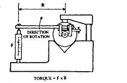
Fig. 15.38. Locked-torque test.
Locked-torque Test.
When the armature is locked the motor produces its maximum torque and consumes its maximum current. Any high resistance in the motor reduces current, so that the torque is lowered. To conduct this test, a torque arm is clamped to the pinion and a spring balance is used to measure the force exerted by the motor (Fig. 15.38). A Lucas 9M90 motor normally produces a maximum torque of 1288 Nm (at 293 K) and draw 3220 W from a 7 V supply.
Running-torque Test.
In this test, the torque is measured through a dummy flywheel fitted on a special test bench, which loads the motor and simulates the resisting torque of an engine. The output torque T (Nm) and speed n (rpm) are recorded and then power, P = 2n nT/60.
Knowing the input power, the efficiency of the motor is calculated as,
Efficiency = (Output power/Input power) x 100%.
For example at cranking speed, input power to a motor (W – VI) is about 2000 W and output power from the motor (P = 2nnT/60) is about 900 W. Where, V = 10 V; I = 200 A; n = 1200 rpm; andr=7Nm.
![]()
