33.12.
Pressure Control
33.12.1.
Suction Pressure Regulator (SPR)
The suction pressure regulator controls the pressure of the refrigerant in the evaporator by preventing the pressure from falling below a predetermined range, usually 152 kPa to 207 kPa depending upon the system design. If a setting of 207 kPa is assumed, the suction pressure regulator releases evaporator pressure to the compressor if it is above 207 kPa, thus maintains a constant pressure of 207 kPa in the evaporator. The operation of evaporator in this manner is satisfactory provided the thermostatic expansion valve, suction regulator, and compressor function properly.
The flow through any type of suction pressure regulator is never completely stopped. A bypass system is included so that a small amount of refrigerant and refrigeration oil can circulate through the system. This provision eliminates the possibility of compressor damage if the suction regulator closes due to malfunctioning.
33.12.2.
Evaporator Pressure Regulator (EPR)
The evaporator pressure regulator valve (Fig. 33.44), a fully automatic suction pressure control device, is used in certain automotive air conditioning systems. It is located inside the compressor and just under the suction side service valve, as shown in Fig. 33.45.
The valve maintains the evaporator pressure between 152 kPa to 179 kPa and thus its temperature is just above freezing. Inside the valve, the control spring pressure and the evaporator refrigerant pressure maintain a balance. A diaphragm seals the chamber and prevents refrigerant leakage. An increase of evaporator pressure causes the control spring to move the valve away from the seated position and as a result there is an increase in the refrigerant flow from the evaporator to the compressor. Similarly, a decrease in evaporator pressure restricts the flow of refrigerant from the evaporator so that the evaporator pressure increases until the evaporator pressure regulator valve opens. Opening and closing of the valve continues until a balance is established between the evaporator pressure and the spring tension. The valve then remains in a constant position unless the evaporator heat load or the compressor speed changes, and a new balance of pressure is required. Any malfunction of the valve requires replacement as it cannot be repaired.

Fig. 33.44. Evaporator suction pressure regulator valve location.

Fig. 33.45. Evaporator suction pressure regulator valve and oil return passage.

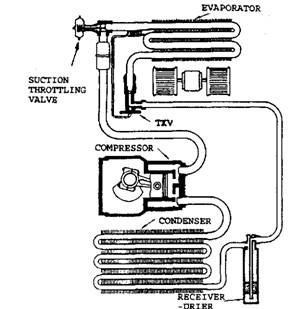
Fig. 33.46. Location of the pilot operated absolute suction throttling valve.
The oil passage inside the compressor between the suction line and the compressor crankcase also runs through the,,*vaporator pressure regulator valve. This passage allows the oil to be returned to the crankcase. In addition, the oil passage pressurizes the crankcase and prevents the crack-case pressure from dropping below the normal atmospheric pressure, thereby entry of outside air is avoided.
33.12.3.
Suction Throttling Valve (STV)
It is a flow control device installed at the evaporator outlet of some automotive air-conditioning systems (Fig. 33.46) to maintain the evaporator pressure at a predetermined level. This type of valve controls more accurately than many other types of controls. It holds the evaporator pressure to an accuracy of + 3.4 kPa (+ 0.5 psig).
The valve uses a pilot valve that enables it to achieve a pressure very close to the absolute zero pressure. The absolute pilot exerts pressures opposite to the evaporator pressure and hence does not rely on spring pressures or atmospheric pressure for its operation. Two fittings on the valve accommodate the oil bleed line and the external equalizer line of the expansion valve. The pilot valve requires proper adjustment. If the valve becomes defective, it requires total replacement as it is a sealed unit and cannot be serviced.
33.12.4.
Valves-in-receiver (VTR)
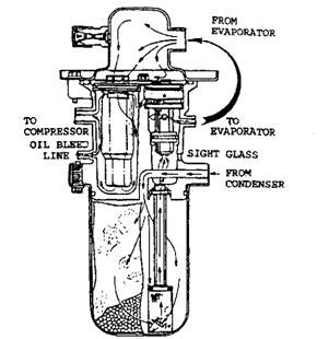
The valves-in-receiver assembly (Fig. 33.47) is a combination of three different components; the thermostatic expansion valve, the suction throttling valve, and the receiver-dehydrator (including a sight glass). The cutaway section of valves-in-receiver assembly is shown in Fig. 33.48, along with direction of refrigerant flow. The later series are called evaporator equalizer valves-in-receiver (EEVIR). Both the types of valve assemblies operate and are serviced in the same manner.

Fig. 33.47. Typical valves in receiver installation.

Fig. 33.48. Cutaway section of valves in receiver.
The valves-in-receiver assembly is mounted near the evaporator. Both the inlet and outlet fittings of the evaporator connect to the valves-in-receiver, as well as the liquid line (condenser outlet) and the suction line (compressor inlet). The valve is designed to eliminate the need for the equalizer external capillary and the thermostatic expansion valve remote bulb. The diaphragm end of the thermostatic expansion valve is exposed directly to refrigerant vapour entering the valves in receiver from the outlet of the evaporator. The provision for external equalizing consists of a small orifice (hole) drilled in the housing wall between the suction throttle valve and the thermostatic expansion valve. The desiccant is contained in the receiver shell and is replaceable. A liquid pickup tube containing a filter screen extends to the bottom of the shell. The filter traps impurities and prevents them from circulating through the system. A replaceable sight glass is located in the valves-in-receiver housing at the

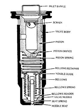
Fig. 33.49. Thermostatic expansion valve.

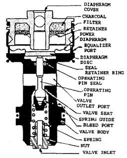
Fig. 33.50. Suction throttle valve.
inlet of the thermostatic expansion valve. Figs. 33.49 and 34.50 show the thermostatic expansion valve and suction throttle valve respectively installed in valves-in-receiver.
