33.11.
Electrical Circuits and Devices
The basic automotive air-conditioning electrical circuit is simple as shown in Fig. 33.39. Generally, it consists of a fuse or circuit breaker, a master ON/OFF and blower speed control, a thermostat, a blower motor, and a clutch coil. The heater system utilizes the same fuse or circuit breaker and blower motor as those used for the air-conditioning system in most factory installed units. Additional electrical circuits provide warning signal during under-heating and overheating conditions of engine coolant. Such a warning system may be a tell-tale dash light or a dash gauge.
33.11.1.
Fuses
The fuse or circuit breaker protects the air-conditioning and heating components including wiring, and usually has a rating of 20 to 30 A. Two types of fuses are currently being used in domestic automobiles. One type consists of a thin ribbon of flat wire, which is enclosed in a glass tube with metal ends. The other type is also a thin ribbon of flat wire, but is enclosed in a plastic case and has metal ends. One type is not replaceable with other.

Fig. 33.39. Typical circuit of automotive air-conditioning.
Circuit breakers are constructed of a bimetallic strip and a set of points (contacts). Heating due to excessive current causes the bimetallic strip to bend as a result of which the points open. This stops current flow, consequently the bimetallic strip cools and the point automatically reset (close). The action continues until the cause of the problem is corrected or the circuit breaker fails due to fatigue.
33.11.2.
Master Control
The master control generally includes provisions for the blower speed control, and a rheostat. A variable resistor is used for speed control. A four-speed control circuit uses three internal resistors to control motor speed. Greatest resistance in the circuit results in a low speed and no resistance results in a high speed. Generally, the blower motor speed control is also the master ON/OFF control. The blower switch in ON position provides full battery voltage to the control thermostat.
33.11.3.
Thermostat
Thermostat, a means of temperature control, is used for the control of the electromagnetic clutch of the compressor. It is basically an electrical switch, which is actuated by a change in temperature. It senses either evaporator core temperature or the temperature of the refrigerant as it enters or leaves the evaporator. Above or at and below a specified temperature it respectively closes or opens the thermostatic switch. This in turn sends or interrupts the electrical signal to the clutch. Thereby the compressor cycles switch on and off through the clutch at the setting point to control the average temperature inside the car. Most thermostats have a positive OFF position so that the clutch can be turned off regardless of the temperature. This helps to operate the air-conditioner blower or fan without a refrigerating effect.
Two types of thermostats are in use for the control of the clutch; the bellow type and the bimetallic type. Although the principle of operation is different for each type of thermostat, but both are temperature actuated and are adjustable.
Bellows Type Thermostat.
The principle of construction of the bellows type thermostat is shown in Fig. 33.40. It has a bellows attached to a capillary tube filled with a temperature-sensitive fluid. The bellows, in-turn, is attached to a swinging frame assembly fastened to an
electric contact point through an insulator. The other contact point is fastened to the body of the unit, also through an insulator.

Fig. £3.40. Schematic of a bellows type thermostat.
When the gas inside the capillary tube expands, pressure is exerted on the bellows, which closes the electrical contacts at a pre-selected temperature. A spring installed in the thermostat regulates the temperature interval through which the points are opened. This interval usually corresponds to a temperature rise of about 6.6 degrees and gives sufficient time for the evaporator to defrost.
Bimetallic Type Thermostat.
The bimetallic-type thermostat (Fig. 33.41) has no capillary tube, and is of low cost. When cold air passes over the bimetallic leaf at the rear of the thermostat, it causes forming the bows to retract enough to open a set of points. As the temperature increases, the other leaf of the bimetallic element reacts to the heat and pulls the points back together. The OFF cycle period of this thermostat is also 6.6 degrees. The bimetallic thermostat has limited application because it requires mounting inside the evaporator.
33.11.4.
Blower Motor
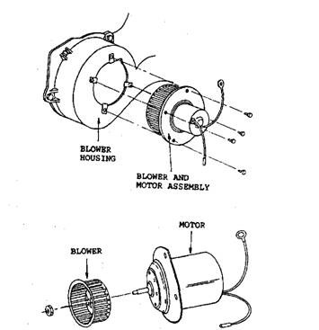
Many types of blower motors are in use, depending upon the application. They may be flange mounted and may have provisions for internal cooling. The blower motor drives one or two squirrel-cage blowers (Fig. 33.41) to move air across the evaporator and/or heater core. The direction of rotation of the motor is important, depending upon blower housing design, to ensure air flow.
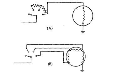
If motor speed control is carried out by resistors, the motor requires only one winding, as shown in Fig. 33.42A. The motor speed control can also be achieved by multi-wound motors, as shown in Fig. 33.42B. Resistance for speed control is provided by the motor windings and hence external resistors are not required. The figure represents a three speed system and the switch is shown in OFF position.
Common causes of failure of automotive blower motors include worn bushings or brushes, or defective internal wiring. These motors are generally not repairable, hence if found defective have to be replaced.

Fig. 33.41. Squirrel-case blower, attached to the blower motor.

Fig. 33.42. Fan /blower speed control. A. Resistors in a typical switch. B. Multi-wound motor with internal resistance.
33.11.5.
Electromagnetic Clutch
As indicated in section 33.6.4, automotive air-conditioning compressors use an electromagnetic clutch to engage and disengage the compressor from the engine. The compressor is disengaged when a defrost cycle is indicated in the evaporator or when the air conditioner is not being used. The electromagnetic clutch operates on the principle of magnetic attraction. There are two general types of clutches; those with a stationary field and those with a rotating field. The stationary field clutch has fewer rotating parts than a rotating field clutch.
Stationary Field Clutch.
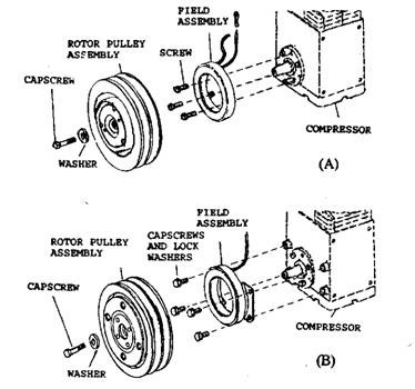
In this type of clutch, the field winding is mounted to the compressor by mechanical means (Fig. 33.43) depending upon the type of field and the compressor. The rotor is held on the armature by means of a bearing and snap rings. The armature is mounted on the compressor crankshaft.
When the thermostat or switch is closed, current is applied to the field winding and a magnetic force is established between the field winding and the armature due to which the armature is pulled into the rotor. The complete unit turns while the field winding remains stationary and hence the compressor starts. When the thermostat or switch is opened, the current to the field winding is cut off. The armature disengages from the rotor and field winding stops while the rotor continues to turn. As a result the compressor stops.

Fig. 33.43. Stationary field clutch. A. Seal-mounted clutch field winding. B. Boss-mounted clutch field winding.
Rotating Field Clutch.
This type of clutch operates in the same manner as the stationary field clutch. In this layout, the field winding is a part of the rotor and turns with the rotor. Current is applied to the field winding by means of brushes, which are mounted on the compressor. When current is applied, the complete unit, consisting of the armature, rotor, and field winding turns and causes the compressor to rotate.
The spacing between the rotor and armature should be accurate to avoid dragging and slippage. With too less spacing, the armature is dragged on the rotor when the clutch is turned off. If the spacing is large, slippage occurs and contact becomes poor. The spacing between the rotor and the pulley is also important. The pulley should be as close to the coil as possible for better travel of magnetic flux, but the rotor should not be dragged on the coil housing.
33.11.6.
Pressure Cut-off Switch
Many systems have a low and a high pressure cut-off switch in the clutch circuit. These normally closed switches are sensitive to system pressure and open in the event of abnormal pressure, causing disengagement of the clutch.
The low pressure cut-off switch is placed between the evaporator outlet and the compressor inlet. The high-pressure cut-off switch is installed between the compressor outlet and the receiver inlet. When the low or high side pressure limit is reached, the compressor is stopped through the respective cut-off switches; thereby the system is prevented from damage due to excessive low or high pressure condition.
33.11.7.
Compressor Discharge Pressure Switch
This switch is located in the discharge line between the compressor outlet and the receiver inlet and stops the compressor by disengaging the clutch if the refrigerant charge is not adequate (due to leak etc). The switch is activated when the high-side system pressure drops below 255 kPa. This switch also performs the secondary function of an ambient air temperature sensor.
When outside air temperature falls below 269 K ( – 4 C), the corresponding reduced refrigerant pressure keeps the switch open. This switch is also called a no-charge, ambient low-temperature switch, or a low-pressure cut-off switch.
