33.10.
Control Devices
In a modern automobile, control devices are used to actuate door locks, deck lids, head lamp covers, windows, seats, antennas etc. In this section, only the devices used to control air conditioning and heating system functions are discussed. Control devices perform directly or indirectly through lever, cable, vacuum or electricity.
33.10.1.
Heater Control
The heater control valve may be located on the engine, on the fender well, near the heater core, or inside the heater case. The control valve is actuated by a cable (Fig. 33.28). For the automatic temperature system, the control is vacuum operated and is governed by varying vacuum levels. A typical vacuum operated control valve for hot water heater is shown in Fig. 33.29. The combined water pressure and spring pressure helps to keep the valve in closed position. In normal operation, the opening of the valve can be varied to control the water flow (Fig. 33.30).

Fig. 33.28. Cable controlled water valve.

Fig. 33.29. Typical vacuum actuated hot water control valve.

Fig. 33.30. Hot water valve flow control.
Actually, a pulsating effect is more likely to occur at automobile speeds above 85.5 km/h when water pressure is high. This condition has a specific effect on the operation of the temperature control.
Since one of the primary functions of an automatic temperature control system is to maintain a relative humidity of45-50% inside the car, the hot water valve is controlled to allow a small amount of engine coolant to enter the heater system. The hot air from heater core is mixed with the cooler air from the compartment and then the mixed air is passed through the air conditioner evaporator to maintain the desired humidity level.
33.10.2.
Vacuum Operated Mode Doors
Vacuum operated mode doors include the temperature deflector, diverter, defroster, outside-inside inlet, and heater-air-conditioner outlet doors. For various conditions, there are number of combinations of door positions. Air conditioner and heater duct systems (section 33.14) cover various mode door positions in detail. Mode doors are used to divert air from one passage to another. Mode doors are operated manually or remotely. Vacuum motor is used for automatic operation.
Temperature Door.
The temperature door regulates the air mixture. The position of the temperature mode door determines the temperature of the duct air in an automatic temperature control system. The temperature door is operated by a vacuum motor, a temperature door actuator, or a servo. Fig. 33.31 represents the mode door operation with vacuum motors.
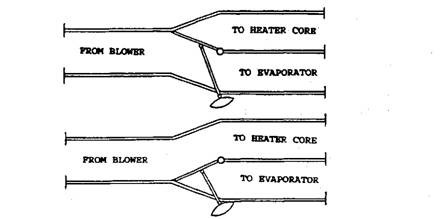
Fig. 33.31. Air diverter door with vacuum motor.
Most vacuum motors are of the type shown in Fig. 33.24, having only one vacuum hose attachment. Some units shown in Fig. 33.32, called double action vacuum motors, have double
action diaphragms which allow a vacuum to be applied to either side. Some automatic temperature control units using double action vacuum motors are known as temperature door actuator (TDA).
33.10.3.
Blower Control
The blower control permits for a high or low volume of air flow. The high volume air flow is necessary during maximum utility load. The air flow varies automatically with the demand on the system (which varies with weather conditions). The blower control is carried out electrically, not by vacuum. The vacuum controlled servo uses electrical contacts similar to the vacuum switch section of the servo.
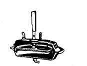
Fig. 33.32. Double-action vacuum motor.
33.10.4.
Time-delay Relay
The time delay control unit is designed to delay the action of the heat cycle in the automatic unit until the engine coolant has reached a temperature of 316.5 K. The unit, shown in Fig. 33.33, uses two resistors, capacitors and transistors.

Fig. 33.33. Circuit diagram of time-delay relay.
33.10.5.
Electro-vacuum Relay (EVR)
The electro-vacuum relay incorporates a normally closed vacuum solenoid valve and normally closed electrical relay. The purpose of the EVR is to delay blower operation when the system is in the “heat” mode until engine coolant temperature reaches 319 to 322 K. When the coolant temperature is below this value, electrical contacts in the engine temperature switch are closed. This grounds and completes the EVR circuit to open the engine temperature switch relay contacts, which are in series with the blower motor so that current to the motor is interrupted to open the circuit.
33.10.6.
Ambient Switch
The ambient switch is used in many automatic systems, which is an electrical switch actuated by changing the ambient temperature. The ambient switch is located outside the engine area where it can sense the ambient temperature only. If the master switch is pressed, the ambient switch turns the air conditioning compressor ON at 275 K. The switch turns the compressor OFF if the ambient temperature falls to 269 K. Whenever the ambient temperature is in the range of 291 to 286 K; the ambient switch bypasses the master control and time-delay relay and allows the blower to run regardless of the engine coolant temperature.
When the air conditioning compressor or blower is operated at low ambient temperature, the humidity of the incoming air is reduced by condensing moisture from it. This prevents window fogging when an automobile is being operated during rainy, damp, or cool weather conditions.
33.10.7.
Thermostatic Vacuum Valve (TW)
The thermostatic vacuum valve (Fig. 33.34) is a vacuum control valve, sensitive to temperature. It is used only on late model automatic systems and is mounted where it can sense coolant temperature, such as on the side of the heater core. It consists of a power element cylinder with a piston, vacuum parts, and spring. The power element is filled with a temperature-sensitive compound so that when the engine is cold and the coolant is not warm, the inlet part of the TW is blocked and the outlet part is vented. When the coolant temperature reaches a specified range, usually 311 to 325 K, the compound in the cylinder expands and moves the piston till vacuum flow starts. On cold days, it serves only as a time-delay.
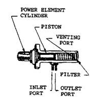
Fig. 33.34. Thermostatic vacuum valve.
33.10.8.
Superheat Switch
The superheat switch is located in the rear head of some six cylinder compressor. This device is a temperature/pressure sensitive electrical switch, which is normally in the open position as shown in Fig. 33.35, during high temperature and high pressure conditions or low-temperature and low pressure conditions of the system. The switch closes when the system experiences high temperature and low pressure conditions, which is usually caused by a loss of refrigerant. The superheat switch offers a fail-safe method of stopping the compressor, as a safe guard against the damage to the compressor as well as the system due to loss of refrigerant. When the superheat switch closes, a circuit is completed through the thermal fuse heater. The fuse blows, opens the clutch circuit, and stops the compressor. The latest models of the superheat switch (Fig. 33.35B) do not have the thermal sensing tube, like earlier models (Fig. 33.35A).
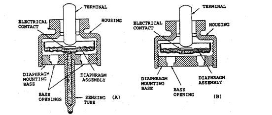
Fig. 33.35. Superheat switch in sectional view.
33.10.9.
Thermal Fuse
The thermal fuse works with the superheat switch to protect the compressor as described above. It consists of a temperature sensitive fuse and a wire-wound resistor (heater), mounted as one assembly as shown in Fig. 33.36. When the superheat switch closes, a ground point is created in the clutch circuit and hence current supplied to the compressor now flows through the thermal fuse heater to the ground. As the heater warms, the fuse link material reaches its melting point. Melting of the link causes the clutch circuit to open so that clutch action stops.
33.10.10.
Check Valve and Relays
Check Valve.
The use of a check valve and reserve tank is explained in the section 33.9.2. The check valve is opened whenever the manifold vacuum is greater than the reserve vacuum i.e. it is opened by the normal engine vacuum, and connects the source to the tank as well as allows vacuum from the control to reach the vacuum motor. Whenever manifold vacuum drops below the reserve pressure, which normally happens during acceleration period and when engine is stopped, the check valve closes and blocks the passage from the control to the motor. The vacuum reserve is used to operate the vacuum system.
Check Relay.
The vacuum check relay, shown schematically in Fig. 33.37, prevents a vacuum loss during low manifold vacuum conditions and the system mode operation during such periods. Like the
check valve, the check relay is to be replaced when found defective as it can not be repaired.
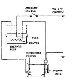
Fig. 33.36. Thermal fuse in the clutch circuit.
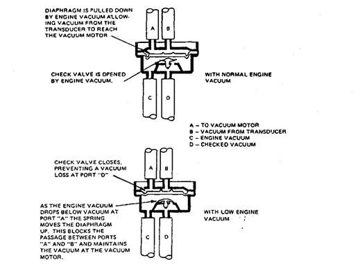
Fig. 33.37. Check relay.
33.10.11.
Thermostatic Vacuum Switch (TVS)
The purpose of the thermostatic vacuum switch (Fig. 33.38) is to protect the engine from overheating during prolonged idle periods at high ambient temperature and with or without
operation of the air conditioner. Therefore, strictly speaking, it is not a part of the air-conditioning system.
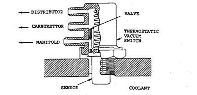
Fig. 33.38. Thermostatic vacuum switch.
The TVS is located in the coolant passage of the thermostatic housing. It uses three vacuum hoses ; one connects to the carburettor, another to the intake manifold, and the third to the distributor advance mechanism. Normal distributor vacuum provisions are off the carburettor throttle plate. The amount of vacuum applied to the advance from the source is proportional to engine speed. At curb idle speed practically no vacuum signal is provided, hence there is no vacuum advance. Once the engine coolant temperature exceeds safe limits, usually 380 K, the thermal sensor of TVS shifts the vacuum valve and full manifold vacuum is applied to the distributor vacuum advance mechanism.
This, in-tern, advances engine timing and increases engine speed due to which a greater volume of coolant flows through the cooling system. Airflow through the radiator also increases. Thus engine operating temperature comes down. When the coolant temperature falls below the critical point, the vacuum valve shifts to its normal position and engine speed returns to the normal idle condition.
