9.6.
Air Cleaner-cum-filter
Air contains dirt, abrasives and other contaminates which cannot be allowed to reach the engine. Like fuel filters, an air cleaner-cum-filter (Fig. 9.26) are used to remove contaminates from the air. It has three primary functions. (i) to clean air before mixing with fuel (ii) to silence intake noise
(Hi) to act as a flame arrestor in case of a backfire.
It also helps for more efficient carburettor adjustments, which reduces exhaust emissions without reducing engine performance, permits cleaner air-fuel ratios, gives better fuel economy, and reduces carburettor icing in cold weather. As the particles are trapped they plug the filter pores. Excessive plugging restricts air flow into the engine and this upsets the carburettor setting. Air filter plugging produces a rich fuel mixture, which in turn reduces engine power, and increases carbon monoxide and unburned hydrocarbon in exhaust emissions. Badly plugged air filters limit engine power and speed. It is best to replace a filter element before it becomes too dirty to be effective. A dirty air filter element allows contaminants, which causes engine wear and increases fuel consumption.
The air cleaner shown in Fig. 9.26, usually located on the top of the carburettor, is clamped to the air horn, and generally has a snorkel or air intake tube. The cleaner housing is circular in two-pieces, made of stamped steel.
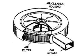
Fig. 9.26. Simple air cleaner-cum-filter.

Fig. 9.27. Paper air filter element.
Air filters may be classified as dry filters and oil-bath filters. The latter have better performance under worst conditions and hence are widely used. The paper air filter element (Fig. 9.27) is the most common type used in automobiles. Chemically treated paper is pleated and formed into a circle, with the top and bottom edge sealed with heat-resistant plastic. A fine wire mesh screen is used on the inside of the filter ring to reduce the possibility of the element catching fire from an engine backfire. A similar, but coarser, wire mesh screen is used on the outer side of the filter ring for extra strength.
Latest versions of air filters use resin-impregnated paper-element, which provide higher efficiency at lower cost with simpler maintenance. Additionally, they are lighter, more compact and do not require supplementary support brackets. Some varieties of air filters incorporate centrifugal extraction of larger particles by means of abrupt changes in the airflow path by deflector vanes and catchment louvers. Some models are also available with built in carburettor silencers, which contain sound damping passages, suitable resonance chambers or sound absorbent pads.
Figure 9.28 shows a sectional view of an oil-bath air filter. Air enters at the circumferential gap of the filter and passes down the annular space to the restricted gap at the oil level. Air impinges on the oil surface at high velocity after the right angle turn due to which heavier particles from air are deposited in the oil bath. Oil-laden air then reverses upward into the filter element containing oil-wetted mesh of metal wool where the finer particles are arrested after which cleaned air passes down the vertical intake to the carburettor. The air filter is designed to be placed on top of the carburettor and to be clamped to the air horn.
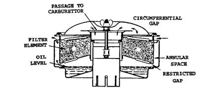
Fig. 9.28. Oil-bath air filter.
Air filters need periodic cleaning depending on extent of operation. Oil-bath filters are cleaned by washing in paraffin or petrol and then refilled with oil of correct grade to the required level. Oil of same viscosity and grade as used in the engine is normally used for this type of air filter.
Air mainly enters the carburettor through the air cleaner snorkel. Some air cleaners are fitted with a second snorkel to provide additional air intake at full throttle. The air from the snorkel passes to the filter and then to the carburettor from the engine compartment. The snorkel also helps to increase the velocity of the air entering the air cleaner. Temperature in the engine compartment often exceed 365 K on a hot day, and hot air can thin out the air-fuel mixture sufficiently to cause deterioration and possible engine damage. To prevent this problem the engine is allowed to breathe cooler air from outside the engine compartment. Cooler air flows through a cold air duct, or induction tube. The tube runs from the snorkel to a fresh air intake at the front of the car. It uses a screen to prevent insects and other foreign matters from being drawn into the air cleaner. The fresh air intake is normally open at all times.
9.6.1.
Thermostatically Controlled Air Cleaners
Recent air cleaners have thermostatic controls to regulate intake air temperature. This is necessary to maintain precise air-fuel ratios required for controlling exhaust emission. The thermostatically controlled air cleaner has the usual sheet metal housing mounted on the carburettor air horn. Another sheet metal duct, called a heat stove or shroud, is placed around the exhaust manifold. The heat stove is connected to the air cleaner intake snorkel by a flexible hose or metal tube (Fig. 9.29). Heat radiating from the exhaust manifold is kept in by the heat stove, and then released to the air cleaner snorkel to provide heated air to the carburettor.
An air control valve, or damper, in the snorkel permits the intake of heated air from the heat stove, cooler air from the snorkel or cold air duct, or a combination of both. The damper maintains intake air at a specified temperature, usually between 305 K and 310 K. The damper is operated by a vacuum motor or diaphragm or by a thermostatic bulb. In an air cleaner using a vacuum motor, a bimetal temperature sensor and a vacuum bleed in the air cleaner housing regulate vacuum supply to the vacuum motor. Vacuum is supplied from the intake manifold. When intake air temperature is below 310 K, the temperature sensor holds the vacuum bleed closed and full manifold vacuum is applied to the vacuum motor. The motor holds the air control valve in the full-hot-air position (Fig. 9.30A). As intake air warms up, the sensor
begins to open the vacuum bleed. This decreases the vacuum going to the motor. A spring installed in the motor then starts to move the air-control valve from the hot air to the cold-air position (Fig. 9.30B). As air temperature rises, the vacuum bleed continues to open; thereby vacuum to the motor is further reduced. At high air temperature, vacuum to the air cleaner
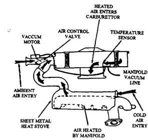
Fig. 9.29. Thermostatically controlled air cleaner with heat stove.
motor is completely closed, and the air control valve is in its full-cold-air position (Fig. 9.30C). The air control valve also opens to the full-cold-air position during high acceleration, regardless of air temperature. This provides maximum airflow through the air cleaner to the carburettor when it is needed the most.
The thermostatic bulb, used to control some air cleaners, is placed inside the air cleaner snorkel and is connected by linkages to a spring-loaded air control valve, or damper. The air control valve is normally held in its closed position by the spring, allowing heated intake air to enter the snorkeKFig. 9.31A). As the temperature rises, the thermostatic bulb begins to expand. This expansion is more than air valve spring tension, and hence the valve gradually opens to its cold-air position (Fig. 9.31B).
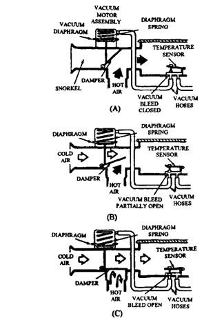
Fig. 9.30. Thermostatically controlled air cleaner with vacuum motor control.
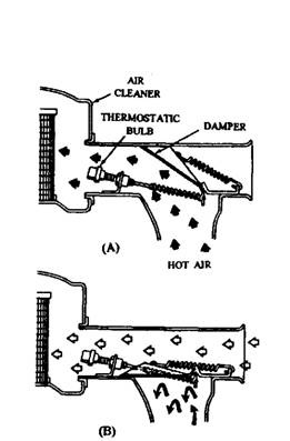
Fig. 9.31. Thermostatically controlled air cleaner with thermostatic-bulb control.
