18.5.
Additional Engine Management Functions
18.5.1.
Pulse Air Injection
Some vehicles use pulse air injection systems to supply fresh air to the catalyst just after engine starting when the engine is operating with an enriched mixture. This supports oxidation of unburned hydrocarbons within the catalyst, enabling it to quickly reach operating temperature and thereby reducing pollutant emissions from a cold engine. For the operation of pulse air injection system, the engine management ECU actuates a solenoid valve to open a passage between the inlets and exhaust manifolds. Pulsations of the gas in the exhaust manifold then
draw fresh air into the exhaust system to react in the catalyst. As soon as the engine warms up the air injection valve is closed.
18.5.2.
Electrically Heated Catalysts
Electrically heated catalysts (EHCs) have been developed to tackle the problem of high pollutant emissions which prevail in the first 30-60 seconds of operation after a cold start. Such devices are expected to be used incresingly as emission regulations become more stringent so that systems such as pulse air injection are no longer feasible.
Early prototype EHCs used normal catalyst structures, which were heated by a current of 300 A for the first 30 seconds of engine operation. Subsequently the catalytic element is thermally isolated from its container with an air-gap and by mounting it on tiny ‘pin’ supports, so that the heating requirement has been reduced to 50-100 A for 5 seconds. Recent EHCs have a small volume so they are mounted directly up-stream of the main three way catalyst, which operates when the engine has warmed up.
The ECU switches on the current to the EHC, just as the engine fires, and heats up the catalyst element, which soon gains further heat due to exothermic chemical reactions that take place. An operating temperture of about 673 K is reached 15 seconds after engine has started and the catalyst attains 90% efficiency after about 40 seconds of the start so that heating current can be switched-off at this point.
18.5.3.
Variable Intake Air-flow Control
During the normal operation of an engine the continuous flow of the intake air provides a ‘ram’ effect, which helps purging of exhaust gas from the cylinder causing optimum cylinder charging. At low engine speeds the intake air velocity is required to be high to overcome exhaust gas pressure in the cylinder. This high velocity is achieved through a long and narrow intake tract. On the other hand, at high engine speeds the intake air velocity is already high and so a short, large diameter, intake tract is necessary to reduce flow resistance. These conflicting requirements can be met by installing two intake tracts for each cylinder. A main intake tract and a second (bypass) tract are fitted with a disc valve. The engine ECU electronically controls the position of the disc valve according to engine speed (Fig. 18.17). At low

Fig. 18.17. Operation of inlet manifold tract bypasses valves.
speed the bypass valve is kept closed, so that all of the intake air is forced to flow at high velocity through the main tract. At high speed the valve is held fully open to allow flow of intake air with least resistance. At medium engine speed the valve is slightly opened so that a dip in output torque is prevented at the transition between the two modes of operation. Either by a solenoid-controlled vacuum diaphragm or a servo-motor actuates the bypass valve, the latter method, however, provides a more precise control of valve position.
18.5.4.
Evaporative Emission Control System
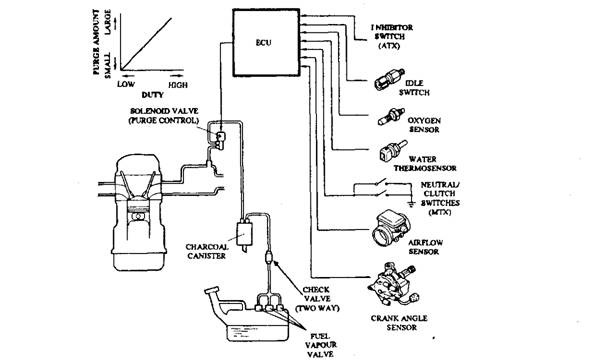
The evaporative emission control system (Fig. 18.18) draws and burns the HC emissions from the vehicle’s fuel tank.

Fig. 18.18. Evaporative emission control system (Mazda).
Evaporative fumes are drawn from the fuel tank, pass through a check valve and are temporarily stored in a charcoal canister. The quantity of fumes drawn into the engine and burned is regulated by a duty-cycle controlled solenoid valve in accordance with preprogrammed values stored in the ECU’s memory, which correspond to a variety of engine operating conditions. The solenoid valve is opened only when
(i) the engine is warm,
(H) the driving is in a gear,
(Hi) the engine is above idle speed, and
(iv) the oxygen sensor is functioning normally.
