18.4.
Closed-loop Engine Control System
Systems using the open-loop principle can only follow a program set-up after testing a prototype engine in a first-class mechanical condition. If the engine does not maintain the similar condition then the timing and fuel settings become incorrect. This problem can be well understood by highlighting the job of setting the ignition timing of an older type engine with the help of a strobe light. The timing, however, may be set to the angle recommended by the manufacturer, but it may not be correct setting for the actual engine being tuned, because the recommended setting is applicable for new engine and the older engine may not be in a similar condition.
These problems can be minimized by using a closed-loop control system. This control system can work independently to control ignition and fuel metering systems or can be applied to the combined ignition and fuel metering system to provide a full engine management.
18.4.1.
Ignition Control
The ideal ignition timing for an engine is the point where combustion is just free from knock. It is difficult to obtain this setting accurately without special equipment, because knock occurs before it can be detected by the human ear. Factors that affect the maximum spark advance before the onset of knock include,
• Mechanical condition of engine,
• Compression ratio,
• Octane rating of fuel,
• Volumetric efficiency,
• Throttle opening,
• Shape of combustion chamber,
• Air-fuel ratio,
• Engine temperature, and
• Carbon deposits.
A very sophisticated open-loop system using many sensors along with an elaborate map containing a very large number of ignition angles is necessary to cover all these variables in a program. Since this is impracticable, a normal open-loop system with a simpler map is used. This map provides suitable ignition angles to meet general needs maintaining a margin of safety for the engine to keep it free from knock and damage. To obtain better power and improved emissions with this arrangement, use of a sensitive knock control system is necessary. When closed-loops control system is used in combination with a lambda map, the feedback signal generated by the knock sensor allows the adjustment of the spark timing to set just knock-free combustion in the chamber.
At the beginning, the timing is set by using the data from the map. The ECU then advances this basic timing setting until the knock sensor signals a given degree of knock. The timing advance is then reduced in steps of 1.5 crankshaft degrees until the sensor indicates that the engine is knock-free. The continual repetition of this sequence maintains optimum ignition time angle for each individual cylinder (Fig. 18.14).

Fig. 18.14. Knock control system.
The signals from the knock sensor can also be used in a turbocharged engine to control the boost of the turbo-charger. When the engine is operating under full-load conditions and the sensor detects the knock, the feedback signal activates a command signal to open the turbo-charger’s waste-gate and reduce the boost.
A safety circuit is incorporated in the knock-control system to detect malfunctions of the system. Once a fault is recognized, a warning light on the instrument panel is activated and also the ignition timing advance is reduced accordingly to prevent damage to the engine.
18.4.2.
Closed-loop Dwell-angle Control
The dwell-angle control ensures obtaining the correct primary current under variations in battery voltage, in engine speed and in temperature. This is specifically important during cold starting of the engine because at this stage much lower voltage then normal is applied to the coil. To compensate this, a longer time must be allowed for the primary current to build-up that means the dwell must be lengthened. On the other hand, if the dwell angle is set too large, then power loss and heating of the ignition system take place.
Like other closed-loop systems, the dwell-angle control circuit incorporates a feedback circuit, which signals if the primary current exceeds a predetermined value so that the dwell-angle is reduced accordingly by its control action.
18.4.3.
Fuel Control
It is necessary to use a closed-loop fuel control system to meet the severe emission regulations. The open-loop systems used initially to control fuel supply and ignition settings could not satisfy the regulations that came into force in later years. To meet the very stringent controls over emissions, it became necessary to incorporate a catalytic converter in the exhaust system to convert pollutants by chemical means into safe products. The three way catalytic converters effectively oxidize CO, HC and NOx, pollutants. However, the chemical converter
can be used effectively only when the engine is operated very close to the chemically correct mixture ratio. Hence an efficient feedback control system capable of maintaining the air-fuel ratio in the required region is necessary,
18.4.4.
Lambda Sensor
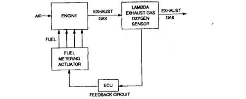
A lambda closed loop system fulfills mixture control requirement to meet most emission regulations. This arrangement uses a sensor in the exhaust system, which detects mixture strength being burnt in the engine cylinders. Signals fed back from this sensor enable the fuel-control system to vary appropriately the fuel quantity whenever the sensor detects either a too rich or too weak mixture.
The lambda sensor is an oxygen sensor, which produces a voltage pulse when no oxygen is present in the exhaust gas, this condition can only occur when the air-fuel ratio is on the higher side of stoichiometric (chemically correct) ratio. The system layout (Fig. 18.15) shows the feedback circuit through which the digital pulse signals passes when oxygen is present in the exhaust gas. The principle of the lambda exhaust gas oxygen (EGO) sensor is also described under section 9.24.2.

Fig. 18.15. Closed-loop fuel control system.
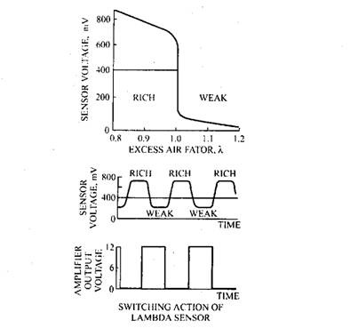
When the sensor signals that the oxygen content is below a certain limit, a voltage pulse from the EGO sensor instructs fuel system to decrease the fuel supply to weaken the mixture. Soon after this fuel alteration the EGO sensor senses the presence of oxygen in the gas, due to which its voltage output falls and as a result the output from the sensor changes to zero. When the controller receives no feedback signal, it directs the fuel system to enrich the mixture. Thus mixture control is achieved by oscillating the mixture strength between the rich and weak limits. This enables the controller to keep the air-fuel ratio within a range that is near correct. Since modern sensors work to a very small tolerance with respect to the air-fuel ratio, it is possible to control exhaust emission very accurately. A limit of 0.05 in air-fuel ratio from the required value of 14.7:1 is typical for many sensors.
The variation of voltage with respect to the air-fuel ratio is illustrated in Fig. 18.16. The abrupt change in voltage between the points where X is greater than 1.0 and X is less than 1.0 is the region where the voltage pulse is produced for use as an output signal. This signal provides a limit-control type of cycle so that the EGO sensor works like a switch, which opens and closes to signify weak and rich mixtures respectively. The EGO provides a digital output with the two states, 0 and 1 used to identify the weak and rich mixtures.

Fig. 18.16. Operation of lambda sensors.
This control system is expected to operate very fast, so the mixture adjustment must respond very quickly to electronic control signals. To achieve this the use of either an electronic carburettor or fuel-injection system is inevitable.
The EGO sensor does not function efficiently below about 573 K. Therefore when the exhaust temperature transducer detects the mean temperature of the exhaust gas below this minimum temperature, the engine-control system is switched to the open-loop mode. This mode is used during cold-starting, when the engine is idling, and at times when the control system detects a fault in the EGO sensor circuit.
Situations arise during acceleration and deceleration when the engine has to be operated outside the range of the EGO sensor. At these occasions the other sensors signal the engine condition to the ECU which selects the open-loop mode to operate until normal steady conditions are re-established. A lead-free fuel is necessary for the EGO sensor to operate.
