Correlation Properties
The Gold codes are selected as spreading sequences for the GPS signals because of their characteristics. The most important characteristics of the C/A codes are their correlation properties. These properties are described now.
The two important correlation properties of the C/A codes can be stated as follows:
Nearly no cross correlation All the C/A codes are nearly uncorrelated with each other. That is, for two codes![]() for satellites i and k, the cross correlation can be written as
for satellites i and k, the cross correlation can be written as
Nearly no correlation except for zero lag All C/A are nearly uncorrelated with themselves, except for zero lag. This property makes it easy to find out when two similar codes are perfectly aligned. The autocorrelation property for satellite k can be written as
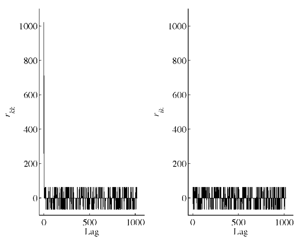
Figure 2.6 shows an example of the auto- and cross-correlation properties of the C/A code. As expected, the figure shows high correlation at lag 0 when correlating with the same C/A code, and low correlation when correlating with another C/A code.
FIGURE 2.6. Correlation properties of the C/A codes. Left: Autocorrelation![]() of the C/A code for PRN 1. Right: Cross correlation
of the C/A code for PRN 1. Right: Cross correlation![]() of the C/A codes for PRNs 1 and 2.
of the C/A codes for PRNs 1 and 2.
The autocorrelation shown in the left part of Figure 2.6 has a peak of magnitude
where n is the number of states in the shift registers. In this case, n equals 10. The remaining values satisfy the following inequality, Gold (1967):
For n = 10, we get
The cross correlation in the right part of Figure 2.6 also satisfies the inequality in (2.11).
Doppler Frequency Shift
In GPS we are faced with a Doppler frequency shift caused by the motion of the transmitter (satellite) relative to the GPS receiver. The Doppler frequency shift affects both the acquisition and tracking of the GPS signal. For a stationary GPS receiver the maximum Doppler frequency shift for the L1 frequency is around ![]() and for a GPS receiver moving at high speed it is reasonable to assume that the maximum Doppler shift is
and for a GPS receiver moving at high speed it is reasonable to assume that the maximum Doppler shift is![]()
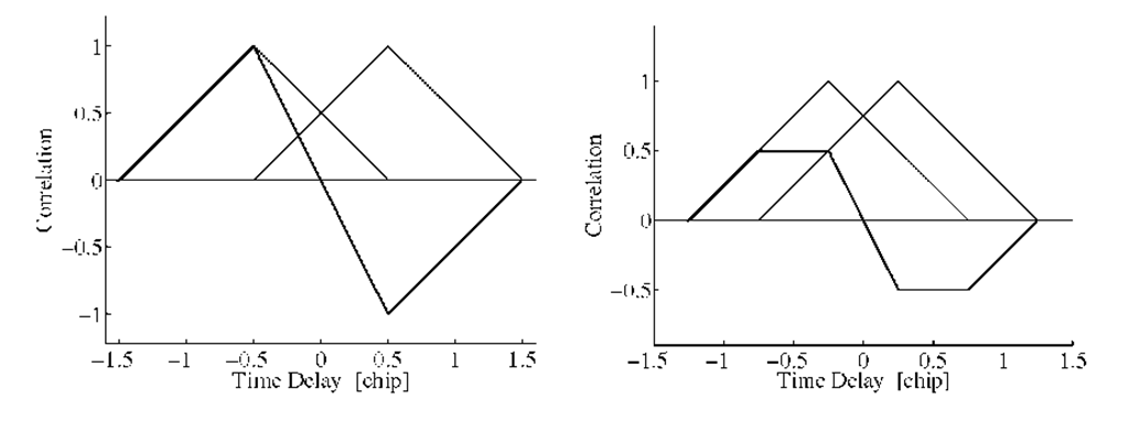
FIGURE 2.7. The two triangles indicate the early and the late ACF. In the left part the two triangles are separated by d = 1 chip (classical wide correlator), and the right part shows a separation of d = 0.5chip (narrow correlator). Both discriminators have the same slope close to the origin.
The Doppler frequency shift on the C/A code is small because of the low chip rate of the C/A code. The C/A code has a chip rate of 1.023 Mhz, which is 1575.42/1.023 = 1540 times lower than the L1 carrier frequency. It follows that the Doppler frequency on the C/A code is 3.2 Hz and 6.4 Hz for the stationary and the high-speed GPS receiver, respectively.
The Doppler frequency on the C/A code can cause misalignment between the received and the locally generated codes and the values of the Doppler frequency are important for the tracking method.
Code Tracking
GPS signal receiving involves a classical problem, namely that one of code tracking which can be solved by means of the delay-locked loop (DLL) scheme based on an early-late discriminator.This loop-error detector or loop discriminator is—in its simplest version—based on a two-correlator structure. Each correlator is set with a small time offset relative to the promptly received signal code timing phase, both producing early and late signals. Combining the early and late signals provides an error signal, driving the loop toward elimination of the delay-tracking error.
The code tracking loop can be designed as a – coherent delay lock loop (DLL), or a – noncoherent DLL.
The coherent DLL requires the phase lock loop to be in lock, i.e., it is tracking the carrier phase and the navigation data bits have been removed from the signal. The noncoherent DLL is able to track the code with the navigation data bit present and the PLL is not necessarily in lock. The noncoherent design is the preferred one; see Winkel (2000).
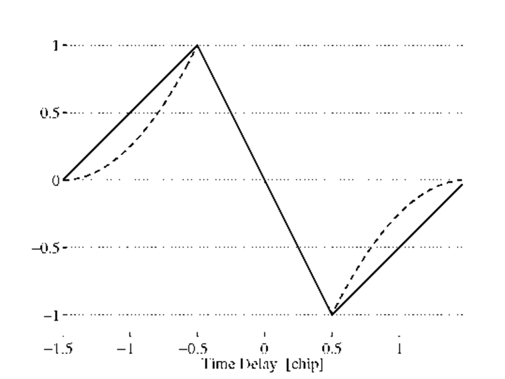
FIGURE 2.8. Coherent (full line) and noncoherent (dashed line) discriminator functions.
The input signal is split into two paths and correlated with two versions, an early and a late, of a locally generated PRN code. The two versions are equally spaced, typically![]() about the prompt PRN code. This is done for both the in-phase I branch and the quadrature Q branch. The estimation of the ACF in all six signals
about the prompt PRN code. This is done for both the in-phase I branch and the quadrature Q branch. The estimation of the ACF in all six signals![]() , where E denotes early, L denotes late, and P denotes promptly, is based on a summation of the respective signals over an interval of time T. Often T equals s corresponding to the bit duration of the navigation bits. In this time interval the data bit is constant. The GPS signal structure implies that the duration of one navigation data bit divided by one chip duration is an integer (20,460).
, where E denotes early, L denotes late, and P denotes promptly, is based on a summation of the respective signals over an interval of time T. Often T equals s corresponding to the bit duration of the navigation bits. In this time interval the data bit is constant. The GPS signal structure implies that the duration of one navigation data bit divided by one chip duration is an integer (20,460).
The ACF for the signals discussed above can be used to set up the corresponding code discriminators. The early minus late discriminator is obtained by subtracting a late copy of the correlation function from an early copy. The correlator spacing d between the early and the late code is set to 0.5 chip; see Figure 2.7.
The code tracking loop is a device that estimates the signed time difference between the received and the reference code. The zero of this detector is the pseu-dorange or code phase observation. Null tracking is enabled by subtracting the late correlation from the early correlation. The resulting difference is called the discriminator function. For a coherent DLL we have![]()
For a noncoherent DLL, the discriminator function is
Navigation Data
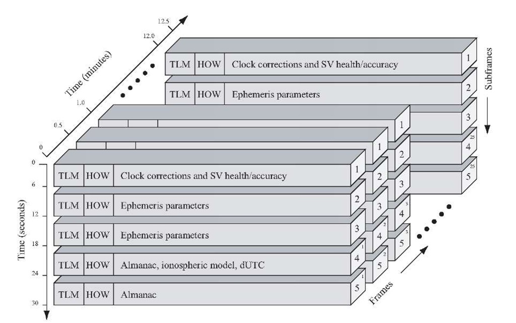
The navigation data are transmitted on the L1 frequency with the earlier mentioned bit rate of 50 bps. This section describes the structure and contents of the navigation data. Figure 2.9 shows the overall structure of an entire navigation message.
FIGURE 2.9. GPS navigation data structure. Each subframe containing 300 bits lasts 6 s. Subframes 1, 2, and 3 repeat every 30 s while subframes 4 and 5 have 25 versions before repeating. That is, the entire navigation message repeats after 12.5 minutes.
The basic format of the navigation data is a 1500-bit-long frame containing 5 subframes, each having length 300 bits. One subframe contains 10 words, each word having length 30 bits. Subframes 1, 2, and 3 are repeated in each frame.With the bit rate of 50 bps, the transmission of a subframe lasts 6 s, one frame lasts 30 s, and one entire navigation message lasts 12.5 minutes.
Telemetry and Handover Words
The subframes of 10 words always begin with two special words, the telemetry (TLM) and handover word (HOW) pair.
TLM is the first word of each subframe and it is thus repeated every 6 s. It contains an 8-bit preamble followed by 16 reserved bits and parity. The preamble should be used for frame synchronization.
HOW contains a 17-bit truncated version of the time ofweek (TOW), followed by two flags supplying information to the user of antispoofing, etc. The next three bits indicate the subframe ID to show in which of the five subframes in the current frame this HOW is located.
Data in Navigation Message
In addition to the TLM and HOW words, each subframe contains eight words of data. This will only be a cursory description of the data in the different words and not a complete description of all bits.
Subframe 1 - Satellite Clock and Health Data The first subframe contains first of all clock information. That is information needed to compute at what time the navigation message is transmitted from the satellite. Additionally, subframe 1 contains health data indicating whether or not the data should be trusted.
Subframes 2 and 3 - Satellite Ephemeris Data Subframes 2 and 3 contain the satellite ephemeris data. The ephemeris data relate to the satellite orbit and are needed to compute a satellite position.
Subframes 4 and 5 - Support Data As mentioned, the last two subframes repeat every 12.5 minutes, giving a total of 50 subframes. Subframes 4 and 5 contain almanac data. The almanac data are the ephemerides and clock data with reduced precision. Additionally, each satellite transmits almanac data for all GPS satellites while it only transmits ephemeris data for itself. The remainder of subframes 4 and 5 contain various data, e.g., UTC parameters, health indicators, and ionospheric parameters.
For a more in-depth description of the contents of the navigation data, see SPS (1995).
![tmp2D407_thumb[2][2] tmp2D407_thumb[2][2]](http://what-when-how.com/wp-content/uploads/2012/02/tmp2D407_thumb22_thumb.png)
![tmp2D408_thumb[2][2] tmp2D408_thumb[2][2]](http://what-when-how.com/wp-content/uploads/2012/02/tmp2D408_thumb22_thumb.png)


