Straddling Elements
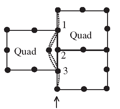
Straddling elements can also result in mesh incompatibility, as illustrated in Figure 11.14. Although the order of the shape functions of these connected elements is the same, the straddling can result in an incompatible deformation of edges between nodes 1 and 2, and 2 and 3, as indicated by the dotted lines in Figure 11.14. This is because in the assembly of elements, the FEM requires only the continuity of the displacements (not the derivatives) at nodes between elements.
The method for fixing the problem of the mesh incompatibility of straddling elements is to make sure that there are no straddling elements in the mesh. Most mesh generators are designed not to produce such an element mesh. However, care needs to be taken in the process of creating a mesh manually.
Figure 11.14. Incompatible mesh caused by straddling along the common edge of the same order of elements.
Use of Symmetry
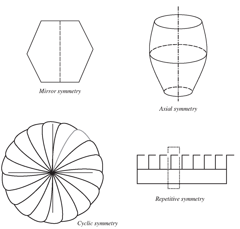
Many structures and objects exhibit some form of symmetry. Figure 11.15 shows the different types of common structural symmetry. Objects such as a drinks can can exhibit axial symmetry, and even huge structures such as the Eiffel Tower in Paris exhibits mirror symmetry. An experienced analyst will take full advantage of such symmetries in structures to simplify their modelling process, as well as to reduce the DOFs and hence computational time required for the analysis. Imagine a full finite element model of the Eiffel Tower consisting of, say, 100,000 elements. Because of the mirror symmetry, one can actually perform the analysis by modelling just a quarter of the whole structure, and the number of elements will be reduced to just 25,000 elements. The total DOFs of the system will also be reduced to a quarter. Using Eq. (11.1) with a = 3, it can be found that the CPU time will be reduced to (1 /4)3 = (1/64)th of that required for solving the full model. The significance is astonishing! Furthermore, as only a quarter model is required, the time taken for the analyst to create the model is also reduced. In addition, the accuracy of the analysis can be improved as the equation system becomes much smaller and the numerical error in computation will reduce. However, proper techniques have to be used to make full use of the structural symmetry. This section will deal with some of these techniques.
Mirror Symmetry or Plane Symmetry
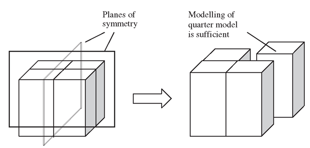
Mirror symmetry is the symmetry about a particular plane, and it is the most prevailing case of symmetry. A half of the structure is the mirror image of another. The position of the mirror is called the plane of symmetry. A structure is said to have mirror structural symmetry if there is symmetry of geometry, support conditions and material properties. Many actual structures exhibit this type of symmetry. Some of these structures are actually symmetrical about a particular plane, while others are symmetric with respect to multiple planes. Take, for example, a cubic block as shown in Figure 11.16. One can actually use the property of single-plane-symmetry and model a half model, or one can use that of two-plane-symmetry to further reduce the finite element model to a quarter of the original structure. In fact, more planes of symmetry can also be used to model just a one-eighth model, and in that case, it would be similar to the case of cyclic symmetry, which will be discussed later.
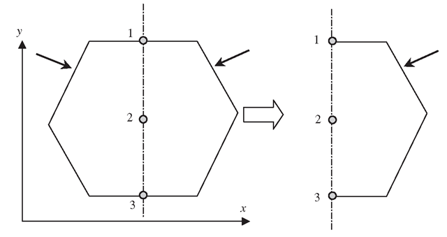
Consider the symmetric 2D solid shown in Figure 11.17. The 2D solid is symmetric with respect to an axis of symmetry of x = c. The right half of the domain is modelled with impositions of the following symmetric boundary conditions at nodes on the symmetric axis:
Figure 11.15. Different types of structural symmetry.
Figure 11.16. Modelling a cubic block with two planes of symmetry.
Figure 11.17. 2D solid with an axis of symmetry at x = c. The right half of the domain is modelled with impositions of symmetric boundary conditions at nodes on the symmetric axis.
where ui(i = 1, 2, 3) denotes the displacements in the x -direction at node i .Equation (11.2) gives a set of Single Point Constraint (SPC) equations, because in each equation there is only one unknown (or one DOF) involved. This kind of SPC can be simply imposed by removing a corresponding row and column in the global system equations, as demonstrated in Examples 4.1 and 4.2.
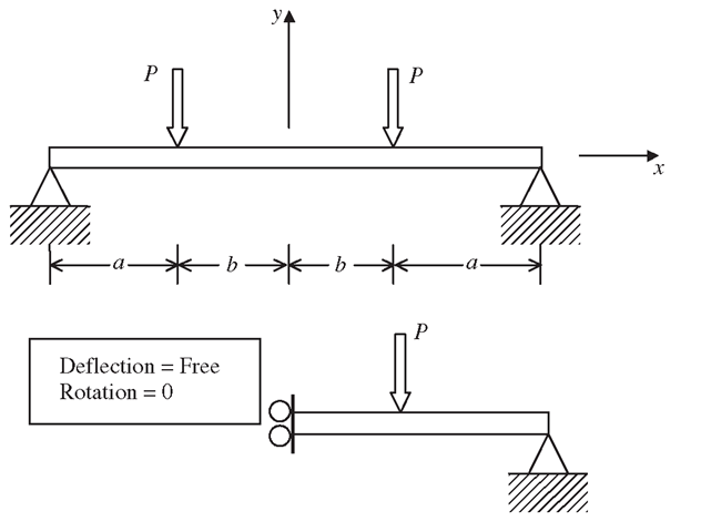
Loading conditions on a symmetrical structure must also be taken into consideration. A loading is considered symmetric if the loading can also be ‘reflected’ off a particular plane, as shown in Figure 11.18. In this case, the problem is symmetric because the whole structure, its support conditions, as well as its loading, is symmetrical about the plane x = 0. An analysis of half of the whole beam structure using the symmetrical boundary condition at x = 0 would yield as complete a solution as that of the full model with at least less than a quarter of the effort.
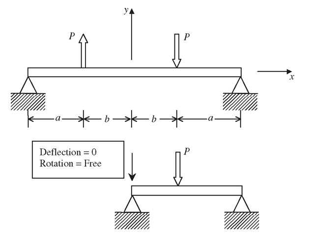
A problem can also be anti-symmetric if the structure is symmetric but the loading is anti-symmetric, as shown in Figure 11.19. Again, modelling half of the structure can also yield a complete solution using an anti-symmetric boundary condition, which would be different on the plane of symmetry. In the simple example shown in Figure 11.19, the anti-symmetric boundary condition is that the deformation at the plane of symmetry is zero. Note that the rotation at the plane of symmetry need not be zero, in contrast with the case of symmetric loading.
Figure 11.18. Simply supported symmetric beam structure.
Figure 11.19. Simply supported anti-symmetric beam structure.
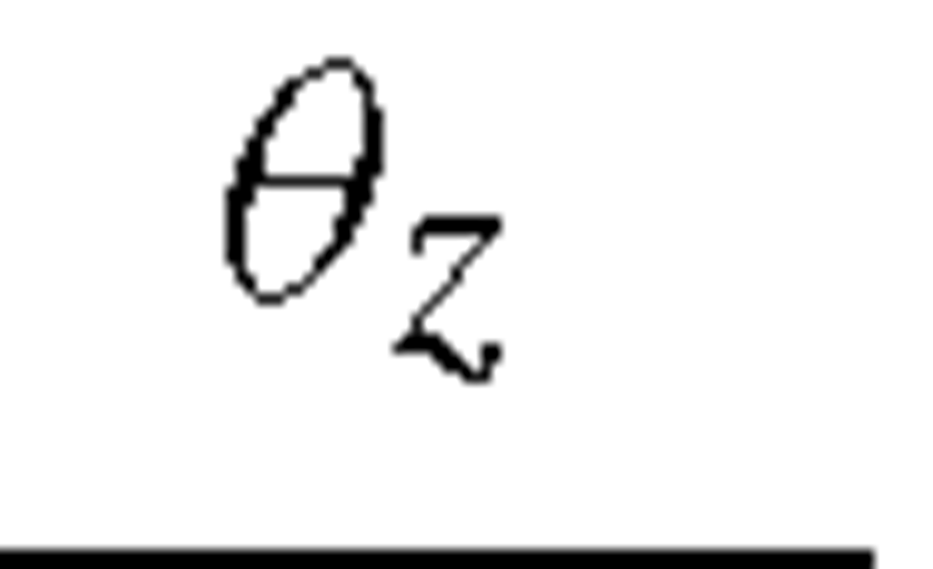
The following general rules can be applied when deciding the boundary conditions at the plane of symmetry. If the problem is symmetric, as shown in Figure 11.18, then:
1. There are no translational displacement components normal to the plane of symmetry.
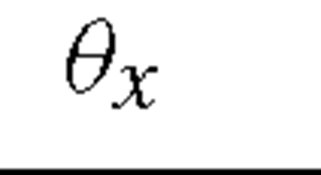
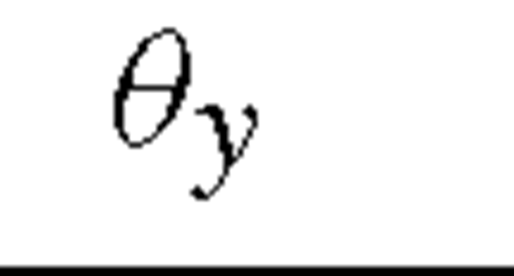
2. There are no rotational displacement components with respect to the axis that is parallel to the plane of symmetry.
Table 11.2. Boundary conditions for symmetric loading
|
Plane of symmetry |
u |
v |
w |
 |
 |
 |
|
xy |
Free |
Free |
Fix |
Fix |
Fix |
Free |
|
yz |
Fix |
Free |
Free |
Free |
Fix |
Fix |
|
zx |
Free |
Fix |
Free |
Fix |
Free |
Fix |
Table 11.3. Boundary conditions for anti-symmetric loading
|
Plane of symmetry |
u |
v |
w |
 |
 |
 |
|
xy |
Fix |
Fix |
Free |
Free |
Free |
Fix |
|
yz |
Free |
Fix |
Fix |
Fix |
Free |
Free |
|
zx |
Fix |
Free |
Fix |
Free |
Fix |
Free |
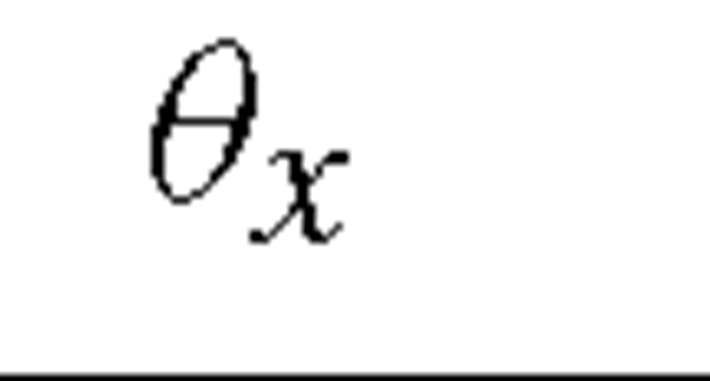
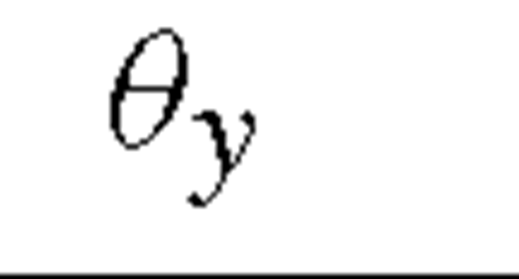
If the problem is anti-symmetric as shown in Figure 11.19, then:
1. There are no translational displacement components parallel to the plane of symmetry.
2. There are no rotational displacement components with respect to the axis that is normal to the plane of symmetry.
Tables 11.2 and 11.3 give a complete list of conditions for symmetry and anti-symmetry for general three-dimensional cases.
Any load can be decomposed into a symmetric load and an anti-symmetric load, therefore as long as the structure is symmetric (in geometry, material and boundary conditions), one can always take advantage of the symmetry. Consider now a case shown in Figure 11.20(a), where the simply supported beam structure is symmetric structurally, but the loading is asymmetric (neither symmetric nor anti-symmetric). The structure can always be treated as a combination of (a) the same structure with symmetric loading, and (b) the same structure with anti-symmetric loading. In this case, one needs to solve two problems, with each problem having half the number of DOFs if the whole structure is modelled. One of the problems is symmetrical while the other is anti-symmetric.
Figure 11.21 shows a more complex example of how a framework with asymmetric loading conditions can be analysed using half of the framework with symmetric and anti-symmetric conditions. Adding up one problem of the same structure subjected to a symmetric loading with another of the same structure subject to anti-symmetric loading is equivalent to analysing the full frame structure with asymmetric loading. In this example, there is actually a frame member that is at the plane of symmetry. The properties of this frame member on the symmetric plane also need to be halved for the two half models. This means that all the properties which contribute to the stiffness matrix for this member need to be halved. If this is a dynamic analysis, then the density also needs to be halved.
Dynamic problems can also be solved in a similar manner using the symmetric or anti-symmetric properties, for example, if symmetric boundary conditions are imposed on a simple beam structure and a natural frequency analysis is carried out.
Figure 11.20. Simply supported symmetric beam structure subject to an asymmetric load. (a) A structure with an asymmetric load; (b) the same structure with a symmetric load; (c) the same structure with an anti-symmetric load.
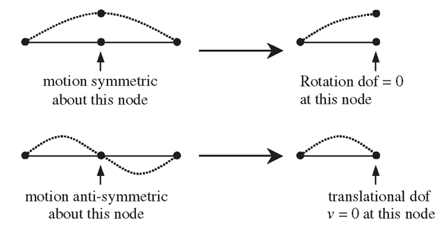
The natural frequencies obtained will correspond only to the symmetrical modes. To obtain the anti-symmetrical modes, anti-symmetrical boundary conditions need to apply to the model. Figure 11.22 shows the symmetric and anti-symmetric conditions for vibration analysis in a simply supported beam.
Figure 11.21. Using symmetry to analyse symmetrical framework with asymmetric loading.
Figure 11.22. Using symmetric and anti-symmetric conditions for free vibration analysis.
Axial Symmetry
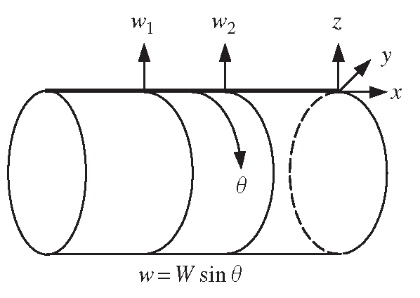
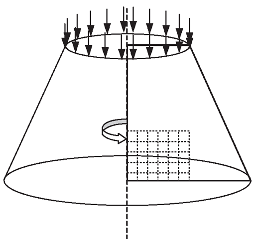
A solid or structure is said to have axial symmetry when the solid can be generated by rotating a planar shape about an axis. Hence, such a solid can be modelled by simply using a special type of 2D or 1D element, called an axisymmetric element. In this way, a 3D solid can be modelled simply by using 1D or 2D elements that will greatly reduce the modelling and computational effort. For example, a cylindrical shell structure can be modelled using 1D axisymmetric beam elements, as shown in Figure 11.23. Figure 11.24 shows an example of a 3D solid under axially symmetric loads, which can be modelled using 2D axisymmetric elements.
Figure 11.23. A cylindrical shell structure modelled using ID axisymmetric elements.
Figure 11.24. A 3D structure modelled using 2D axisymmetric elements.
The formulation of 1D or 2D axisymmetric elements is much similar to the 1D or 2D elements developed in earlier topics, except that all the equations need to be expressed in the polar coordinate system instead of the Cartesian coordination system.Generally speaking, the use of axisymmetric elements requires fewer computational resources compared to a full 3D discretization. Axisymmetric elements are readily available in most finite element software packages, and the use of these elements is similar to their counterpart of regular 1D or 2D elements.
Similar to the plane symmetry problems, the loadings applied on an axial symmetric structure do not have to be axial symmetric or axial anti-symmetric. Any axial asymmetric load can be expressed in a Fourier superimposition of both axial symmetric and axial antisymmetric components in the θ direction (see Figure 11.23). Therefore, the problem can always be decomposed into two sets of axial symmetric and axial anti-symmetric problems, as long as the structure is axial symmetric (in geometry, material and boundary support).
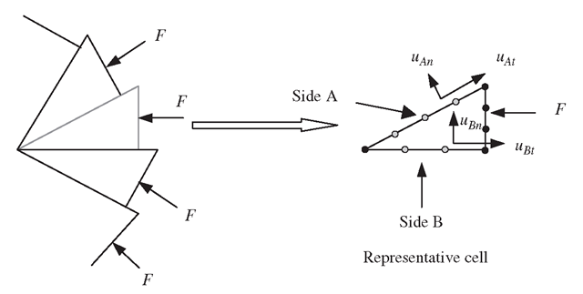
Figure 11.25. Representative cell isolated from a cyclic symmetric structure and the cyclic symmetrical conditions on the cell.
![tmp5896-209_thumb[2] tmp5896-209_thumb[2]](http://what-when-how.com/wp-content/uploads/2012/06/tmp5896209_thumb2_thumb.png)
