Worked Examples
Example 4.1: A uniform bar subjected to an axial force
Consider a bar of uniform cross-sectional area, shown in Figure 4.3. The bar is fixed at one end and is subjected to a horizontal load of P at the free end. The dimensions of the bar are shown in the figure, and the beam is made of an isotropic material with Young’s modulus E.
Exact solution
We first derive the exact solution, as this problem is very simple. From the strong form of governing equation (2.43), we have
Note that, for the current example problem, the bar is free of body forces and hence fx = 0. The general form of solution for Eq. (4.38) can be obtained very easily as
where c0 and C1 are unknown constants to be determined by boundary conditions. The displacement boundary condition for this problem can be given as
Therefore, we have c0 = 0. Equation (4.39) now becomes
Using Eqs. (2.38), (2.39) and (4.41), we obtain
The force boundary condition for this bar can be given as
Equating the right-hand side of Eqs. (4.42) and (4.43), we obtain
Figure 4.3. Clamped bar under static load.
The stress in the bar is obtained by substituting Eq. (4.44) back into Eq. (4.42), i.e.
Substituting Eq. (4.44) back into Eq. (4.41), we finally obtain the solution of the displacement of the bar:
At x = l, we have
FEM solution
Using one element, the bar is modelled as shown in Figure 4.4. Using Eq. (4.15), the stiffness matrix of the bars is given by
There is no need to perform coordinate transformation, as the local and global coordinate systems are the same. There is also no need to perform assembly, because there is only one element. The finite element equation becomes
where F1 is the reaction force applied at node 1, which is unknown at this stage. Instead, what we know is the displacement boundary condition Eq. (4.40) at node1. We can then simply remove the first equation in Eq. (4.49), i.e.
which leads to
This is the finite element solution of the bar, which is exactly the same as the exact solution obtained in Eq. (4.47). The distribution of the displacement in the bar can be obtained by
Figure 4.4. One truss element is used to model the clamped bar under static load.
substituting Eqs. (4.40) and (4.51) into Eq. (4.1),
which is also exactly the same as the exact solution obtained in Eq. (4.46). Using Eqs. (4.37) and (4.14), we obtain the stress in the bar
which is again exactly the same as the exact solution given in Eq. (4.45).
Properties of the FEM Reproduction property of the FEM
Using the FEM, one can usually expect only an approximated solution. In Example 4.1, however, we obtained the exact solution. Why? This is because the exact solution of the deformation for the bar is a first order polynomial (see Eq. (4.46)). The shape functions used in our FEM analysis are also first order polynomials that are constructed using complete monomials up to the first order. Therefore, the exact solution of the problem is included in the set of assumed displacements in FEM shape functions.In Example 4.1, the best possible solution that can be produced by the shape function is the exact solution, due to the reproduction property of the shape functions, and the FEM has indeed reproduced it exactly. We therefore confirmed the reproduction property of the FEM that if the exact solution can be formed by the basis functions used to construct the FEM shape function, the FEM will always produce the exact solution, provided there is no numerical error involved in computation of the FEM solution.
Making use of this property, one may try to add in basis functions that form the exact solution or part of the exact solution, if that is possible, so as to achieve better accuracy in the FEM solution.
Convergence property of the FEM
For complex problems, the solution cannot be written in the form of a combination of monomials. Therefore, the FEM using polynomial shape functions will not produce the exact solution for such a problem. The question now is, how can one ensure that the FEM can produce a good approximation of the solution of a complex problem? The insurance is given by the convergence property of the FEM, which states that the FEM solution will converge to the exact solution that is continuous at arbitrary accuracy when the element size becomes infinitely small, and as long as the complete linear polynomial basis is included in the basis to form the FEM shape functions. The theoretical background for this convergence feature of the FEM is due to the fact that any continuous function can always be approximated by a first order polynomial with a second order of refinement error. This fact can be revealed by using the local Taylor expansion, based on which a continuous (displacement) function u(x) can always be approximated using the following equation:
where h is the characteristic size that relates to (x – Xi), or the size of the element.
One may argue that the use of a constant can also reproduce the function u, but with an accuracy of O(hl), according to Eq. (4.54). However, the constant displacements produced by the elements will possibly not be continuous in between elements, unless the entire displacement field is constant (rigid movement), which is trivial. Therefore, to guarantee the convergence of a continuous solution, a complete polynomial up to at least the first order is used.
Rate of convergence of FEM results
The Taylor expansion up to the order of p can be given as
If the complete polynomials up to the pth order are used for constructing the shape functions, the first (p +1 ) terms in Eq. (4.55) will be reproduced by the FEM shape function. The error is of the order of O(hp+1); the order of the rate of convergence is therefore O(hp+1). For linear elements we have p = 1, and the order of the rate of convergence for the displacement is therefore O(h2). This implies that if the element sized is halved, the error of the results in displacement will be reduced by a rate of one quarter.
These properties of the FEM, reproduction and convergence, are the key for the FEM to provide reliable numerical results for mechanics problems, because we are assured as to what kind of results we are going to get. For simple problems whose exact solutions are of polynomial types, the FEM is capable of reproducing the exact solution using a minimum number of elements, as long as complete order of basis functions, including the order of the exact solution, is used. In Example 4.1, one element of first order is sufficient. For complex problems whose exact solution is of a very high order of polynomial type, or often a non-polynomial type, it is then up to the analyst to use a proper density of the element mesh to obtain FEM results of desired accuracy with a convergence rate of O(hp+1) for the displacements.
As an extension of this discussion, we mention the concepts of so-called h-adaptivity and p-adaptivity that are intensively used in the recent development of FEM analyses. We conventionally use h to present the characteristic size of the elements, and p to represent the order of the polynomial basis functions. h-adaptive analysis uses finer element meshes (smaller h), and p-adaptivity analysis uses a higher order of shape functions (large p) to achieve the desired accuracy of FEM results.
Example 4.2: A triangular truss structure subjected to a vertical force
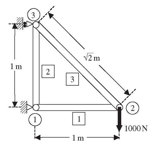
Consider the plane truss structure shown in Figure 4.5. The structure is made of three planar truss members as shown, and a vertical downward force of 1000 N is applied at node 2. The figure also shows the numbering of the elements used (labelled in squares), as well as the numbering of the nodes (labelled in circles).
Figure 4.5. A three member truss structure.
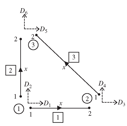
Figure 4.6. Local coordinates and degrees of freedom of truss elements.
The local coordinates of the three truss elements are shown in Figure 4.6. The figure also shows the numbering of the global degrees of freedom, D1, D2,…, D6, corresponding to the three nodes in the structure. Note that there are six global degrees of freedom altogether, with each node having two degrees of freedom in the X and Y directions. However, there is actually only one degree of freedom in each node in the local coordinate system for each element. From the figure, it is shown clearly that the degrees of freedom at each node have contributions from more than one element. For example, at node 1, the global degrees of freedom D1 and D2 have a contribution from elements 1 and 2. These will play an important role in the assembly of the final finite element matrices. Table 4.1 shows the dimensions and material properties of the truss members in the structure.
Table 4.1. Dimensions and properties of truss members
|
Element number |
Cross-sectional area, Ae m2 |
Length le m |
Young’s modulus E N/m2 |
|
1 |
0.1 |
1 |
70 x 109 |
|
2 |
0.1 |
1 |
70 x 109 |
|
3 |
0.1 |
 |
70 x 109 |
Table 4.2. Global coordinates of nodes and direction cosines of elements
|
Element number |
Global node corresponding to |
|
Coordinates in global coordinate system |
Direction cosines |
|
|
Local node 1 (i ) |
Local node 2 (j ) |
 |
 |
 |
|
|
1 |
1 |
2 |
0, 0 1, 0 |
1 |
0 |
|
2 |
1 |
3 |
0, 0 0, 1 |
0 |
1 |
|
3 |
2 |
3 |
1, 0 0, 1 |
 |
 |
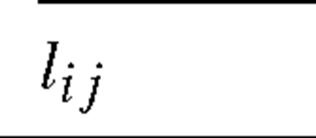
Step 1: Obtaining the direction cosines of the elements Knowing the coordinates of the nodes in the global coordinate system, the first step would be to take into account the orientation of the elements with respect to the global coordinate system. This can be done by computing the direction cosines using Eq. (4.21). Sincethis problem is a planar problem, there is no need to compute nij. The coordinates of all the nodes and the direction cosines of Iij and mij are shown in Table 4.2.
Step 2: Calculation of element matrices in global coordinate system After obtaining the direction cosines, the element matrices in the global coordinate system can be obtained. Note that the problem here is a static problem, hence the element mass matrices need not be computed. What is required is thus the stiffness matrix. Recall that the element stiffness matrix in the local coordinate system is a 2 x 2 matrix, since the total degrees of freedom is two for each element. However, in the transformation to the global coordinate system, the degrees of freedom for each element becomes four, therefore the stiffness matrix in the global coordinate system is a 4 x 4 matrix. The stiffness matrices can be computed using Eq. (4.35), and is shown below:
Step 3: Assembly of global FE matrices The next step after getting the element matrices will be to assemble the element matrices into a global finite element matrix. Since the total global degrees of freedom in the structure is six, the global stiffness matrix will be a 6 x 6 matrix. The assembly is done by adding up the contributions for each node by the elements that share the node. For example, looking at Figure 4.6, it can be seen that element 1 contributes to the degrees of freedom D1 and D2 at node 1, and also to the degrees of freedom D3 and D4 at node 2. On the other hand, element 2 also contributes to degrees of freedom Di and D2 at node 1, and also to D5 and D6 at node 3. By adding the contributions from the individual element matrices into the respective positions in the global matrix according the contributions to the degrees of freedom, the global matrix can be obtained. This assembly process is termed direct assembly.
At the beginning of the assembly, the entire global stiffness matrix is zeroed. By adding the element matrix for element H into the global element, we have
Note that element 1 contributes to DOFs of Di to D4. By adding the element matrix for element [2 on top of the new global element, it becomes
The third equation of Eq. (4.63), which corresponds to the third global DOF, is
The FE equation for element 3 can be written in the following general form:
The first equation of Eq. (4.65), which corresponds to the third global DOF, is
Forces in the x-direction applied at node 2 consist of element force![tmp4454-413_thumb[2] tmp4454-413_thumb[2]](http://what-when-how.com/wp-content/uploads/2012/06/tmp4454413_thumb2_thumb.png) from element 1 and
from element 1 and ![tmp4454-414_thumb[2] tmp4454-414_thumb[2]](http://what-when-how.com/wp-content/uploads/2012/06/tmp4454414_thumb2_thumb.png) from element 3, and the possible external force F3. All these forces have to satisfy the following equilibrium equation:
from element 3, and the possible external force F3. All these forces have to satisfy the following equilibrium equation:
Substitution of Eqs. (4.64) and (4.66) into the foregoing equation leads to
This confirms that the coefficients on the left-hand side of the above equations are the entries for the third row of the global stiffness matrix given in Eq. (4.62). The above proof process is also valid for all the other rows of entries in the global stiffness matrix.
Step 4: Applying boundary conditions The global matrix can normally be reduced in size after applying boundary conditions. In this case, D1, D2 and D5 are constrained, and thus
This implies that the first, second and fifth rows and columns will actually have no effect on the solving of the matrix equation. Hence, we can simply remove the corresponding rows and columns:
The condensed global matrix becomes a 3 x 3 matrix, given as follows:
It can easily be confirmed that this condensed stiffness matrix is SPD. The constrained global FE equation is
where
and the force vector F is given as
Note that the only force applied is at node 2 in the downward direction of D4. Equation (4.72) is actually equivalent to three simultaneous equations involving the three unknowns D3, D4 and D6, as shown below:
Step 5: Solving the FE matrix equation The final step would be to solve the FE equation, Eqs. (4.72) or (4.75), to obtain the solution for D3, D4 and D6. Solving this equation manually is possible, since this only involves three unknowns in three equations. To this end, we obtain
To obtain the stresses in the elements, Eq. (4.37) is used as follows:
In engineering practice, the problem can be of a much larger scale, and thus the unknowns or number of degrees of freedom will also be very much more. Therefore, numerical methods, or so-called solvers for solving the FEM equations, have to be used. Typical real life engineering problems might involve hundreds of thousands, and even millions, of degrees of freedom. Many kinds of such solvers are routinely available in math or numerical libraries in computer systems.
![tmp4454-375_thumb[2] tmp4454-375_thumb[2]](http://what-when-how.com/wp-content/uploads/2012/06/tmp4454375_thumb2_thumb.png)
![tmp4454-376_thumb[2] tmp4454-376_thumb[2]](http://what-when-how.com/wp-content/uploads/2012/06/tmp4454376_thumb2_thumb.png)
![tmp4454-379_thumb[2] tmp4454-379_thumb[2]](http://what-when-how.com/wp-content/uploads/2012/06/tmp4454379_thumb2_thumb.png)
![tmp4454-380_thumb[2] tmp4454-380_thumb[2]](http://what-when-how.com/wp-content/uploads/2012/06/tmp4454380_thumb2_thumb.png)
![tmp4454-381_thumb[2] tmp4454-381_thumb[2]](http://what-when-how.com/wp-content/uploads/2012/06/tmp4454381_thumb2_thumb.png)

![tmp4454-383_thumb[2] tmp4454-383_thumb[2]](http://what-when-how.com/wp-content/uploads/2012/06/tmp4454383_thumb2_thumb.png)
![tmp4454-384_thumb[2] tmp4454-384_thumb[2]](http://what-when-how.com/wp-content/uploads/2012/06/tmp4454384_thumb2_thumb.png)
![tmp4454-385_thumb[2] tmp4454-385_thumb[2]](http://what-when-how.com/wp-content/uploads/2012/06/tmp4454385_thumb2_thumb.png)
![tmp4454-386_thumb[2] tmp4454-386_thumb[2]](http://what-when-how.com/wp-content/uploads/2012/06/tmp4454386_thumb2_thumb.png)
![tmp4454-387_thumb[2] tmp4454-387_thumb[2]](http://what-when-how.com/wp-content/uploads/2012/06/tmp4454387_thumb2_thumb.png)
![tmp4454-388_thumb[2] tmp4454-388_thumb[2]](http://what-when-how.com/wp-content/uploads/2012/06/tmp4454388_thumb2_thumb.png)
![tmp4454-389_thumb[2] tmp4454-389_thumb[2]](http://what-when-how.com/wp-content/uploads/2012/06/tmp4454389_thumb2_thumb.png)

![tmp4454-391_thumb[2] tmp4454-391_thumb[2]](http://what-when-how.com/wp-content/uploads/2012/06/tmp4454391_thumb2_thumb.png)
![tmp4454-392_thumb[2] tmp4454-392_thumb[2]](http://what-when-how.com/wp-content/uploads/2012/06/tmp4454392_thumb2_thumb.png)
![tmp4454-393_thumb[2] tmp4454-393_thumb[2]](http://what-when-how.com/wp-content/uploads/2012/06/tmp4454393_thumb2_thumb.png)
![tmp4454-394_thumb[2] tmp4454-394_thumb[2]](http://what-when-how.com/wp-content/uploads/2012/06/tmp4454394_thumb2_thumb.png)


![tmp4454-403_thumb[2] tmp4454-403_thumb[2]](http://what-when-how.com/wp-content/uploads/2012/06/tmp4454403_thumb2_thumb.png)
![tmp4454-404_thumb[2] tmp4454-404_thumb[2]](http://what-when-how.com/wp-content/uploads/2012/06/tmp4454404_thumb2_thumb.png)
![tmp4454-405_thumb[2] tmp4454-405_thumb[2]](http://what-when-how.com/wp-content/uploads/2012/06/tmp4454405_thumb2_thumb.png)
![tmp4454-409_thumb[2] tmp4454-409_thumb[2]](http://what-when-how.com/wp-content/uploads/2012/06/tmp4454409_thumb2_thumb.png)
![tmp4454-411_thumb[2] tmp4454-411_thumb[2]](http://what-when-how.com/wp-content/uploads/2012/06/tmp4454411_thumb2_thumb.png)
![tmp4454-418_thumb[2] tmp4454-418_thumb[2]](http://what-when-how.com/wp-content/uploads/2012/06/tmp4454418_thumb2_thumb.png)
![tmp4454-420_thumb[2] tmp4454-420_thumb[2]](http://what-when-how.com/wp-content/uploads/2012/06/tmp4454420_thumb2_thumb.png)
![tmp4454-421_thumb[2] tmp4454-421_thumb[2]](http://what-when-how.com/wp-content/uploads/2012/06/tmp4454421_thumb2_thumb.png)
![tmp4454-423_thumb[2] tmp4454-423_thumb[2]](http://what-when-how.com/wp-content/uploads/2012/06/tmp4454423_thumb2_thumb.png)
![tmp4454-424_thumb[2] tmp4454-424_thumb[2]](http://what-when-how.com/wp-content/uploads/2012/06/tmp4454424_thumb2_thumb.png)
![tmp4454-425_thumb[2] tmp4454-425_thumb[2]](http://what-when-how.com/wp-content/uploads/2012/06/tmp4454425_thumb2_thumb.png)
![tmp4454-426_thumb[2] tmp4454-426_thumb[2]](http://what-when-how.com/wp-content/uploads/2012/06/tmp4454426_thumb2_thumb.png)
![tmp4454-427_thumb[2] tmp4454-427_thumb[2]](http://what-when-how.com/wp-content/uploads/2012/06/tmp4454427_thumb2_thumb.png)
