Introduction
A truss is one of the simplest and most widely used structural members. It is a straight bar that is designed to take only axial forces, therefore it deforms only in its axial direction. A typical example of its usage can be seen in Figure 2.7. The cross-section of the bar can be arbitrary, but the dimensions of the cross-section should be much smaller than that in the axial direction. Finite element equations for such truss members will be developed in this topic. The element developed is commonly known as the truss element or bar element. Such elements are applicable for analysis of the skeletal type of truss structural systems both in two-dimensional planes and in three-dimensional space.
In planar trusses there are two components in the x and y directions for the displacements as well as for the forces. For space trusses, however, there will be three components in the x, y and z directions for both displacements and forces. In skeletal structures consisting of truss members, the truss members are joined together by pins or hinges (not by welding), so that there are only forces (not moments) transmitted between the bars. For the purpose of explaining the concepts more clearly, this topic will assume that the truss elements have a uniform cross-section. Therefore, to deal with bars with varying cross-sections, one should develop equations for a truss element with a varying cross-section, which can also be done very easily following the procedure for uniform truss elements. Note that there is no reason from the mechanics viewpoint to use bars with a varying cross-section, as the force in a bar is uniform.
FEM Equations
Shape Function Construction
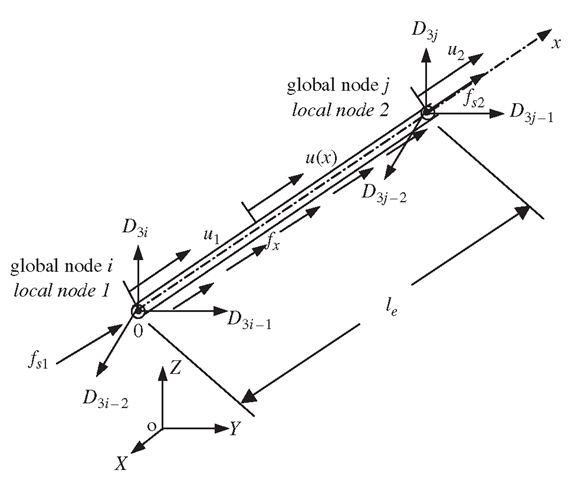
Consider a structure consisting of a number of trusses or bar members. Each of the members can be considered as a truss/bar element of uniform cross-section bounded by two nodes (nd = 2). Consider a bar element with nodes 1 and 2 at each end of the element, as shown in Figure 4.1. The length of the element is le. The local x-axis is taken in the axial direction of the element with the origin at node 1.
Figure 4.1. Truss element and the coordinate system.
In the local coordinate system, there is only one DOF at each node of the element, and that is the axial displacement. Therefore, there is a total of two DOFs for the element, i.e. ne = 2. In the FEM discussed in the previous topic, the displacement in an element should be written in the form
where Uh is the approximation of the axial displacement within the element, N is a matrix of shape functions that possess the properties described and de should be the vector of the displacements at the two nodes of the element:
The question now is, how can we determine the shape functions for the truss elements?
We follow the standard procedure described in Section 3.4.3 for constructing shape functions, and assume that the axial displacement in the truss element can be given in a general form
where uh is the approximation of the displacement, a is the vector of two unknown constants, a0 and a1, and p is the vector of polynomial basis functions (or monomials). For this particular problem, we use up to the first order of polynomial basis. Depending upon the problem, we could use a higher order of polynomial basis functions. The order of polynomial basis functions up to the «th order can be given by
The number of terms of basis functions or monomials we should use depends upon the number of nodes and degrees of freedom in the element. Since we have two nodes with a total of two DOFs in the element, we choose to have two terms of basis functions, which gives Eq. (4.3).
Note that we usually use polynomial basis functions complete of orders, meaning we do not skip any lower terms in constructing Eq. (4.3). This is to ensure that the shape functions constructed will be able to reproduce complete polynomials up to an order of n. If a polynomial basis of the kth order is skipped, the shape function constructed will only be able to ensure a consistency of (k — 1)th order, regardless of how many higher orders of monomials are included in the basis. This is because of the consistency property of the shape function (Property 1),we can expect that the complete linear basis functions used in Eq. (4.3) guarantee that the shape function to be constructed satisfies the sufficient requirements for the FEM shape functions: the delta function property, partition of unity and linear field reproduction.
In deriving the shape function, we use the fact that
Using Eq. (4.3), we then have
Solving the above equation for a, we have
Substituting the above equation into Eq. (4.3), we obtain
which is Eq. (4.1), that we wanted. The matrix of shape functions is then obtained in the form
where the shape functions for a truss element can be written as
We obtained two shape functions because we have two DOFs in the truss elements.
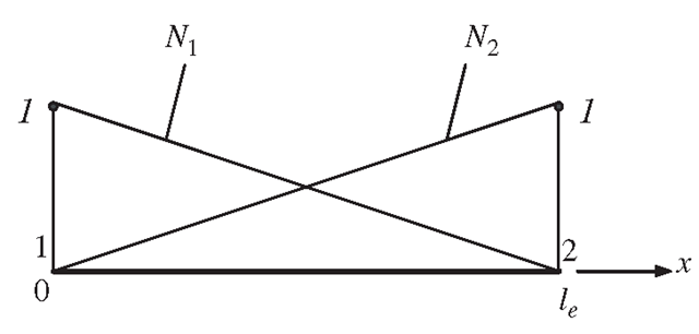
Figure 4.2. Linear shape functions.
It is easy to confirm that these two shape functions satisfy the delta function property defined by Eq. (3.34), and the partitions of unity in Eq. (3.41). We leave this confirmation to the reader as a simple exercise. The graphic representation of the linear shape functions is shown in Figure 4.2. It is clearly shown that Ni gives the shape of the contribution from nodal displacement at node i, and that is why it is called a shape function. In this case, the shape functions vary linearly across the element, and they are termed linear shape functions. Substituting Eqs. (4.9), (4.10) and (4.2) into Eq. (4.1), we have
which clearly states that the displacement within the element varies linearly. The element is therefore called a linear element.
Strain Matrix
There is only one stress component σχ in a truss, and the corresponding strain can be obtained by
which is a direct result from differentiating Eq. (4.11) with respect to x. Note that the strain in Eq. (4.12) is a constant value in the element.
It was mentioned in the previous topic that we would need to obtain the strain matrix, B, after which we can obtain the stiffness and mass matrices. In this case, this can be easily done. Equation (4.12) can be re-written in a matrix form as
where the strain matrix B has the following form for the truss element:
Element Matrices in the Local Coordinate System
Once the strain matrix B has been obtained, the stiffness matrix for truss elements can be obtained using Eq. (3.71) in the previous topic:
where A is the area of the cross-section of the truss element. Note that the material constant matrix c reduces to the elastic modulus, E, for the one-dimensional truss element (see Eq. (2.39)). It is noted that the element stiffness matrix as shown in Eq. (4.15) is symmetrical. This confirms the proof given in Eq. (3.73). Making use of the symmetry of the stiffness matrix, only half of the terms in the matrix need to be evaluated and stored during computation.
The mass matrix for truss elements can be obtained using Eq. (3.75):
Similarly, the mass matrix is found to be symmetrical. The nodal force vector for truss elements can be obtained using Eqs. (3.78), (3.79) and (3.81). Suppose the element is loaded by an evenly distributed force fx along the x-axis, and two concentrated forces fsi and fs2, respectively, at two nodes 1 and 2, as shown in Figure 4.1; the total nodal force vector becomes
Element Matrices in the Global Coordinate System
Element matrices in Eqs. (4.15), (4.16) and (4.17) were formulated based on the local coordinate system, where the x-axis coincides with the mid axis of the bar 1-2, shown in Figure 4.1. In practical trusses, there are many bars of different orientations and at different locations. To assemble all the element matrices to form the global system matrices, a coordinate transformation has to be performed for each element to formulate its element matrix based on the global coordinate system for the whole truss structure. The following performs the transformation for both spatial and planar trusses.
Spatial trusses
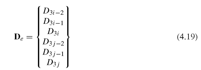
Assume that the local nodes 1 and 2 of the element correspond to the global nodes i and j, respectively, as shown in Figure 4.1. The displacement at a global node in space should have three components in the X, Y and Z directions, and numbered sequentially. For example, these three components at the ith node are denoted by D3i-2, D3i-1 and D3i .The coordinate transformation gives the relationship between the displacement vector de based on the local coordinate system and the displacement vector De for the same element, but based on the global coordinate system XYZ:
where
and T is the transformation matrix for the truss element, given by
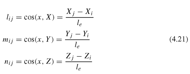
in which
are the direction cosines of the axial axis of the element. It is easy to confirm that
where I is an identity matrix of 2 x 2. Therefore, matrix T is an orthogonal matrix. The length of the element, le, can be calculated using the global coordinates of the two nodes of the element by
Equation (4.18) can be easily verified, as it simply says that at node i, d\ equals the summation of all the projections of![]() onto the local x axis, and the same
onto the local x axis, and the same
can be said for node j. The matrix T for a truss element transforms a 6 x 1 vector in the global coordinate system into a 2 x 1 vector in the local coordinate system.
The transformation matrix also applies to the force vectors between the local and global coordinate systems:
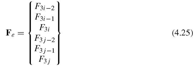
where
in which![]() stand for the three components of the force vector at node i based on the global coordinate system.
stand for the three components of the force vector at node i based on the global coordinate system.
Substitution of Eq. (4.18) into Eq. (3.89) leads to the element equation based on the global coordinate system:
Pre-multiply Tr to both sides in the above equation to obtain:
or
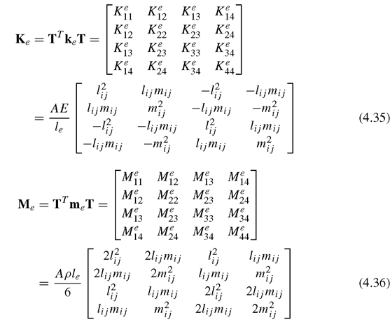
where
and
Note that the coordinate transformation conserves the symmetrical properties of both stiffness and mass matrices.
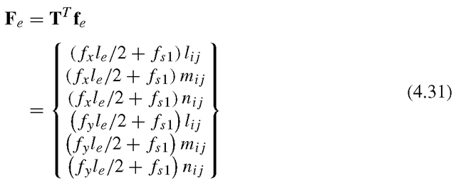
For the forces given in Eq. (4.17), we have
Note that the element stiffness matrix Ke and mass matrix Me have a dimension of 6 x 6 in the three-dimensional global coordinate system, and the displacement De and the force vector Fe have a dimension of 6 x 1.
Planar trusses
For a planar truss, the global coordinates X-Y can be employed to represent the plane of the truss. All the formulations of coordinate transformation can be obtained from the counterpart of those for spatial trusses by simply removing the rows and/or columns corresponding to the z- (or Z-) axis. The displacement at the global node i should have two components in the X and Y directions only: D2i -1 and D2i. The coordinate transformation, which gives the relationship between the displacement vector de based on the local coordinate system and the displacement vector De, has the same form as Eq. (4.18), except that
and the transformation matrix T is given by
The force vector in the global coordinate system is
All the other equations for a planar truss have the same form as the corresponding equations for a space truss. The Ke and Me for the planar truss have a dimension of 4 x 4 in the global coordinate system. They are listed as follows:
Boundary Conditions
The stiffness matrix Ke in Eq. (4.28) is usually singular, because the whole structure can perform rigid body movements. There are two DOFs of rigid movement for planer trusses and three DOFs for space trusses. These rigid body movements are constrained by supports or displacement constraints. In practice, truss structures are fixed somehow to the ground or to a fixed main structure at a number of the nodes. When a node is fixed, the displacement at the node must be zero. This fixed displacement boundary condition can be imposed on Eq. (4.28). The imposition leads to a cancellation of the corresponding rows and columns in the stiffness matrix. The reduced stiffness matrix becomes Symmetric Positive Definite (SPD), if sufficient displacements are constrained.
Recovering Stress and Strain
Equation (4.28) can be solved using standard routines and the displacements at all the nodes can be obtained after imposing the boundary conditions. The displacements at any position other than the nodal positions can also be obtained using interpolation by the shape functions. The stress in a truss element can also be recovered using the following equation:
In deriving the above equation, Hooke’s law in the form of is used, together with Eqs. (4.13) and (4.18).
