Description
A geodetic line, also known the geodesic, is defined as the shortest distance between two points on the surface of the ellipsoid. The geodetic line on the ellipsoid is analogous to a great circle on a sphere. When drawn on a Mercator projection, as shown in Figure 6.9, a geodetic line appears to be curved even though on the ellipsoid it bends neither to the right nor to the left.
If one were to start at any point on the equator and travel a geodetic line to a point on the opposite side of the world, the path would cross either the north pole or the south pole before ending up at the antipole (also on the equator). If one were to leave a point on the equator with a beginning azimuth of, say, 00° 01’, and travel a geodetic line, the path would miss the North Pole and the final destination on the opposite side of the world would be between the antipole and the “liftoff point.” Several comments about the geodetic line:
1. Beginning with an initial azimuth of 00° 01’ on the equator, the geodetic line will miss the North Pole by less than 2 kilometers. Increase the azimuth at the equator to 1°, and the geodetic line misses the pole by something over 111 kilometers.
2. In all cases, there is some point along a geodetic line at which the distance to the pole is a minimum. At that point, the latitude is a maximum and the azimuth of the geodetic line is 90° (see Figure 6.9).
3. The geodetic line has no lateral curvature, but the underlying meridians are not parallel. Therefore, it should be apparent that the azimuth of the geodetic line changes continuously as it traverses the globe. One disadvantage of using a Mercator projection of the world to illustrate the behavior of the geodetic line is that meridians on a Mercator projection are parallel, meaning the geodetic line (which does not curve) must be shown as a curved line.
4. If one starts on the equator and travels east or west along the equator, the path of travel is a geodetic line only until reaching the liftoff point. Beyond that, the equator is not a geodetic line. No other parallel of latitude is a geodetic line.
5. Every point on the ellipsoid has an infinite number of geodetic lines going through it. The azimuth of a geodetic line through a point can have any value between 0° and 360°.
FIGURE 6.9 Geodetic Lines around the Earth
Clairaut’s Constant
An important feature of a geodetic line is that each different line has its own unique number. The number, known as Clairaut’s constant, is defined as
where
N is the ellipsoid normal,
φ is geodetic latitude of the point, and
α is the azimuth of the geodetic line at the point.
Note that the value of Clairaut’s constant will be negative for geodetic line azimuths between 180° and 360°. Also note that while each geodetic line has its own unique constant, the value of Clairaut’s constant does not change as one travels a parallel of latitude. Hence, an unchanging value of Clairaut’s constant is not an exclusive property of a geodetic line.
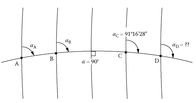
But, a useful feature of Clairaut’s constant is that one can use it to determine the azimuth of a geodetic line at any latitude and, subsequently, the convergence between points. For example, if the azimuth of a line on the GRS80 ellipsoid is 91° 16’ 28” at point C in Figure 6.10 (latitude = 38° 48’ 05.”3342 N), what is the azimuth of the same line at point D (latitude = 38° 12’ 22.”5464 N)? Relating the problem to Figure 6.10 is important because the inverse sine function has two answers. The first answer (typically given by a calculator or computer) will be less than 90°. That would be a correct answer at point A (at the same latitude as point D), as shown in Figure 6.10, but the second correct answer is the supplement (180° – x) of the first.
Solution: first compute Clairaut’s constant using equation 6.65. Then rewrite equation 6.65 to solve for sin α2, as shown in equation 6.66. The inverse sin function will provide two legitimate answers—each is correct at some point on the geodetic line. The user is expected to choose the correct answer of the two.
FIGURE 6.10 Geodetic Line Azimuth Using Clairaut’s Constant
Convergence of the meridians is defined as the difference in azimuth between two points on the same geodetic line.
In the current example, the convergence from C to D is
Knowing that a geodetic line azimuth is 90° (sin 90° = 1) at the maximum latitude, it is also possible to use equation 6.65 to determine the maximum latitude reached by a geodetic line. The solution involves considerable algebraic manipulation, but equation 6.68 is derived by using 1.0 for sin α2.
Finally, the azimuth at which a geodetic line crosses the equator is found from equation 6.65 by using φ2 = 0°, which gives
Geodetic Azimuths
An azimuth is the angle a line on the surface of the Earth makes with the meridian through the same point. The geodetic azimuth on the ellipsoid is the azimuth of the geodetic line, but, when working with 3-D spatial data, it is often more convenient to work with the 3-D azimuth. The two are very nearly identical and, except for very precise applications, can be used interchangeably. Various azimuths are summarized here:
1. If the angle is measured in the horizontal plane defined as perpendicular to the local plumb line, a Laplace correction is required to obtain an equivalent angle in the tangent plane to the ellipsoid at that point.
2. If the angle is referenced to the physical spin axis of the Earth instead of the adopted mean geodetic position of the North Pole, a correction for polar motion is required. The polar motion correction is quite small and beyond the scope of this text. Additional information on polar motion can be found in texts such as Bomford (1971), Vanicek and Krakiwsky (1986), or Leick (2004), or on an appropriate web site.
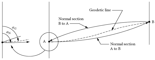
3. When looking through the telescope of a carefully leveled surveying instrument to a target at the other end of the line, there is a common line in 3-D space between point A and point B. A normal section is a line on the ellipsoid from point to point formed by the intersection of a plane containing the normal at the standpoint and the target at the forepoint. Interestingly enough, the normal section from point A to point B on the ellipsoid is not the same as the normal section from point B to point A because the directions of the ellipsoid normals at different latitudes are not parallel. The spatial vector between telescope and target (each way) is common to both planes. But, when the vertical plane at each end of the line is projected to the ellipsoid, the line (normal section) on the ellipsoid from point A to point B will be slightly different than the line from point B to point A. The difference between normal sections is exaggerated and shown in Figure 6.11.
But, a geodetic line is defined as the shortest distance between two points on the ellipsoid surface. Several observations are: first, the geodetic line has no lateral curvature but curves only in the plane containing the instantaneous normal section.
FIGURE 6.11 Normal Sections and the Geodetic Line
Figure 6.11 gives the mistaken impression that a geodetic line has a double curvature. Second, the underlying meridians are not parallel on a globe, but, on a Mercator map, the meridians appear as parallel lines. This explanation for the wrong impression is that a three-dimensional phenomenon is portrayed on a two-dimensional diagram. The important point is that the geodetic line is one line between points on the ellipsoid surface and that the normal sections between points are slightly different depending on whether they are going from point A to point B or from point B to point A.
4. If the angle is measured to a target some distance above or below the ellipsoid, a target height correction may be required. As shown in Figure 6.12, the target height correction is required because the normal through the target (forepoint) is not parallel with the normal through the standpoint (instrument station). The elevation of the theodolite or total station above or below the ellipsoid is immaterial because the vertical axis of instrument is coincident with the vertex of the dihedral angle being measured.
5. The 3-D azimuth lies in the tangent plane at the standpoint and is computed as the inverse tangent of (Ae/An), the local geodetic horizon components of a 3-D vector defined by AX/AY/AZ.
In summary, the following three azimuths are all very close to being identical and are often used interchangeably as a geodetic azimuth. The size of each correction can be used to decide whether the difference is significant or not.
• The geodetic line azimuth is the traditional standard as it is used in geodetic computations on the ellipsoid surface.
• The normal section azimuth is the azimuth of the line on the ellipsoid from standpoint to forepoint (on the ellipsoid) as observed from the standpoint.
FIGURE 6.12 Target Height Correction
• The 3-D azimuth is the spatial direction from the standpoint to the forepoint projected into the tangent plane at the standpoint. The 3-D azimuth is readily obtained from GPS data and is the azimuth utilized in the GSDM.
There are two corrections that relate these three azimuths to each other. One is the target height correction. The other is called the geodesic correction from the normal section to the geodetic line. In many cases, the 3-D azimuth is the one routinely used. If and when a true geodetic line azimuth is required, the logical sequence would be to make the target height correction to obtain the normal section azimuth from the 3-D azimuth, then the geodesic correction is applied to get the geodetic line azimuth from the normal section azimuth.
Target Height Correction
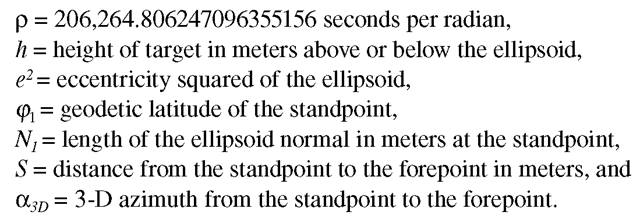
The azimuth of the normal section is computed from the 3-D azimuth by adding the target height correction, as shown in Figure 6.12.
where
Notes related to using the target height correction:
1. Rarely will the target height correction be greater than 0.5 arc seconds.
2. The correction is always added (subtraction is adding a negative number). Whether the correction is positive or negative is determined by sin (2a3D).
3. If using equation 6.70 backwards to compute the 3-D azimuth from the azimuth of the normal section, the normal section azimuth can be used in computing the correction instead of the 3-D azimuth.
Geodesic Correction
Given the azimuth of a normal section, the azimuth of a geodetic line is found by adding a correction, as shown in equation 6.72:
where
Notes regarding use of the geodesic correction:
1. The magnitude of the geodesic correction is quite small and can be ignored in most cases. For example, regardless of standpoint location or azimuth of line, the geodesic correction will never exceed 0.0003 seconds of arc on a 10 kilometer line or 0.03 seconds of arc on a 100 kilometer line.
2. As written, the geodesic correction is a negative value. Depending upon the azimuth of the normal section, the correction may be positive or negative.
3. If equation 6.72 is rewritten to find the azimuth of the normal section given the azimuth of the geodetic line, it is permissible to use the azimuth of the geodetic line in equation 6.73 instead of the normal section azimuth.


