The GSDM is a collection of mathematical concepts and procedures that can be used to manage spatial data both locally and globally. It consists of a functional model that describes the geometrical relationships and a stochastic model that describes the probabilistic characteristics—statistical qualities—of spatial data. The functional part of the model includes equations of geometrical geodesy and rules of solid geometry as related to various coordinate systems and is intended to be consistent with the 3-D geodetic model described by Leick (2004) with the following exception: the GSDM, being strictly spatial, does not accommodate gravity measurements but presumes gravity effects are appropriately accommodated before data are entered into the spatial model. The stochastic portion of the GSDM is an application of concepts described by Mikhail (1976), Leick (2004), and Wolf and Ghilani (1997).
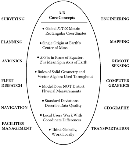
Although the GSDM makes no attempt to accommodate non-Euclidean space or concepts, it does provide a simple universal foundation for many disparate coordinate systems used in various parts of the world and offers advantages of standardization for spatial data users in disciplines such as those listed in Figure 1.1. As such, the GSDM should be viewed as the geometrical portion of a larger concept being promoted as the Global Spatial Data Infrastructure (GSDI) described by Holland et al. (1999) as “[t]he policies, organizational remits, data, technologies, standards, delivery mechanisms, and financial and human resources necessary to ensure that those working at the global and regional scales are not impeded in meeting their objective.” For more information on the GSDI, see http:IIwww.gsdi.org.
Global Spatial Data Model – GSDM (A Universal 3-D Model for Spatial Data)
The Global Spatial Data Model (GSDM) provides a simple, universal 3-D mathematical foundation for the Global Spatial Data Infrastructure (GSDI) which supports Geographic Information System (GIS) database applications in disciplines such as:
FIGURE 1.1 The Global Spatial Data Model
The Functional Model Component
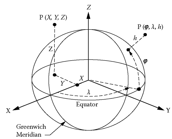
The functional model component of the GSDM is based upon a three-dimensional, right-handed rectangular Cartesian coordinate system with the origin located at the Earth’s center of mass. The X/Y plane lies in the equatorial plane, with the X-axis at the 0° (Greenwich) meridian. The Z-axis coincides with the mean spin axis of the Earth as defined by the Conventional Terrestrial Pole (Leick 2004). This geocentric coordinate system is called an Earth-centered Earth-fixed (ECEF) coordinate system by the United States’ National Imagery and Mapping Agency (1997) and is widely used by many who work with GPS and related data. Rules of solid geometry and vector algebra are universally applicable when working with ECEF coordinates and coordinate differences.
As shown in Figure 1.2, the unique 3-D position of any point on Earth or near space is equivalently defined by traditional latitude/longitude/ellipsoid height coordinates or by a triplet of X/Y/Z coordinates expressed in meters.
FIGURE 1.2 Geocentric XIYIZ and Geodetic φ/λ/h Coordinates
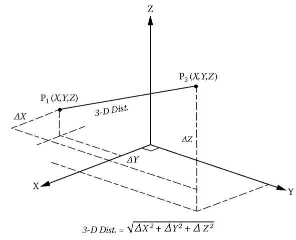
Due to the large distances involved, the X/Y/Z coordinate values can be quite large, but personal computers (PC’s) operating in double precision routinely handle fifteen significant digits. Twelve significant digits will accommodate all ECEF coordinate values within the “birdcage” of GPS satellites down to 0.1 mm. Some users may object to working with such large coordinate values, but, as shown in Figure 1.3, such objections will likely become inconsequential to the extent that end-user applications are designed to utilize coordinate differences (much smaller numbers and fewer digits).
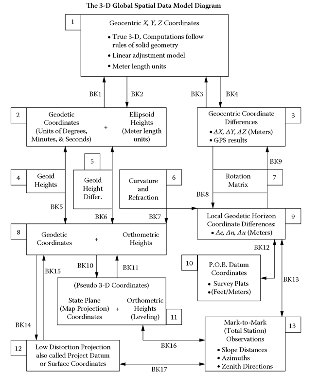
Figure 1.4 is a schematic that illustrates relationships between the ECEF coordinate system and various other coordinate systems commonly used in connection with spatial data.
FIGURE 1.3 GPS Technology Provides Precise AX/AY/AZ Components
FIGURE 1.4 Diagram Showing Relationship of Coordinate Systems
A key feature on the diagram is a rotation matrix used to convert ΔΧ/ΔΥ/ ΔΖcoordinate differences to local Δβ/Δη/Δα coordinate differences at any point (local origin) specified by the user. Since a vector in 3-D space is not altered by moving the origin or by changing the orientation of the reference coordinate system, a vector defined by its geocentric ΔΧ/ΔΥ/ΔΖ components is equivalently defined by local components, and the rotation matrix is the mechanism that efficiently transforms a global perspective into a local one. The transpose of the rotation matrix is used to transform local components of a space vector to corresponding geocentric components.
Computational Designations
With regard to Figure 1.4, the functional model includes equations for transforming spatial data described by coordinates in one numbered box to equivalent expressions in a different coordinate system. The contents of the numbered boxes are as follows:
Box 1: Geocentric X/Y/Z coordinates are the basis for all other coordinate values obtained from the GSDM. These are the primary defining values stored for each point in a digital spatial data file. Coordinate values in other coordinate systems are derived from the stored ECEF coordinates using algorithms that have been tested and proven for mathematical “exactness” and computational precision. This part of the GSDM features meter units, a linear adjustment model, and vector algebra along with universal rules of solid geometry.
Box 2: Geodetic coordinates of latitude and longitude combined with ellipsoid height can define a three-dimensional position with the same precision and exactness as geocentric X/Y/Z coordinates. Equations are listed in a subsequent section by which coordinate values in one box can be converted to equivalent values in another. Using both angular sexagesimal units (degrees, minutes, and seconds) on the ellipsoid and length units of meters for height makes traditional 3-D geodetic computations more complicated than when using ECEF rectangular coordinates.
Box 3: GPS technology has been a driving force behind the use of 3-D spatial data and helps create demand for the GSDM. Although practice includes displaying coordinates in a defined system, the primary output of a GPS survey historically has been a 3-D vector defined by its ΔΧ/ΔΥ/ΔΖ components. Because existing control stations were defined with geodetic coordinates of latitude and longitude (and other reasons), it was natural to continue building a 2-D network using 3-D measurements. And there certainly are cases where that practice can still be justified. But, the GSDM defines an environment in which the full value of 3-D data can be used to build high-quality 3-D networks without being encumbered by 2-D assumptions and complex equations found in classical geometrical geodesy. Another benefit of the GSDM is that the associated stochastic model lends itself to implementation in the rectangular 3-D environment more readily than in the latitude/longitude/height system.
Box 4: In practice, geoid height is taken to be the difference between ellipsoid height and elevation. With any two of the three elements known, the third can be found. If a reliable ellipsoid height for a point (from GPS data) is combined with an appropriate geoid height (from geoid modeling), it is possible to obtain high-quality orthometric height (elevations). Appropriate use of standard deviations for the constituent components will provide a statistical assessment of the quality of such elevations.
Box 5: Box 5 is the same as Box 4 except that the computations are performed using differences.
That means better elevations can be computed by starting with a known high-quality benchmark elevation and combining observed ellipsoid height differences with modeled geoid height differences to compute the orthometric height difference.
Box 6: The Au component from Box 9 is the perpendicular distance of the forepoint from the tangent plane through the standpoint. An elevation difference from the standpoint to the forepoint includes the Au component plus the curvature and refraction (c+r) correction. This c+r procedure is based on the modeled distance between the horizontal plane and a level surface and does not include any geoid modeling between the standpoint and forepoint.
Box 7: Given that the statistical qualities of a vector in space are independent of the perspective from which it is viewed, the rotation matrix is a very efficient method for changing a global perspective (geocentric coordinate differences) into a local perspective (local “flat-Earth” components). Similarly, the transposed rotation matrix converts the local perspective into a global one.
Box 8: Historically, horizontal latitude and longitude coordinates have been combined with vertical elevations when mapping features on or near the Earth’s surface. The generic zero reference surface for elevation has been the geoid (or mean sea level), which admits to a physical definition but, as it turns out, is very difficult, if not impossible, to find. As a result, an arbitrary reference surface that approximates, but does not define, mean sea level was selected for the North American Vertical Datum of 1988 (Zilkoski, Richards, and Young 1992).
Box 9: The local geodetic horizon (Trimble 1990) is essentially the same as the local geodetic frame defined more precisely by Soler and Hothem (1988) and shares many similarities with local plane surveying practice. The primary difference is that “up” is defined by the ellipsoid normal instead of the plumb line. That difference is largely inconsequential except in cases where very high precision is required or where the slope of the geoid (with respect to the normal) is severe. Another difference with the GSDM is that the origin moves with the observer because one is working with local coordinate differences with respect to the user-specified standpoint. See Box 10 for working with a traditional (or fixed) origin.
The Au component in Box 9 can be used as an approximate elevation difference because it does not include the slope of the geoid, Earth curvature, or refraction (c+r)—all inconsequential for short lines. Although suggested as a secondary means for obtaining elevation differences, the standard c+r correction can be combined with the Au component to obtain elevation differences between standpoint and forepoint. Understandably, the primary method for obtaining elevation differences still relies on differential leveling or accurate geoid heights and ellipsoid heights or their differences.
Box 10: Point-of-beginning (P.O.B.) datum coordinates are a feature within the GSDM that accommodates long-established local plane surveying practices without compromising geometrical integrity. P.O.B. coordinates permit the user to select any point in the database as an origin. The 3-D location of each additional point selected is listed with respect to the P.O.B. Admittedly, this practice makes little sense for large distances, but these local coordinate differences can be treated in the same manner as local plane coordinates and used on survey plats. Horizontal distances are in the tangent plane through the P.O.B., and azimuths are with respect to the meridian through the P.O.B. If surveys of adjacent tracts do not use the same P.O.B., there will be two azimuths for a common line (the difference is convergence of the meridians between the two P.O.B.’s). However, if the P.O.B. is the same for both tracts, they will share a common basis of bearing—the geodetic meridian through the P.O.B.
Box 11: Map projections were invented to address the challenge of representing a curved Earth on a flat map. In particular, conformal projections have been used in surveying and mapping to define precisely a 2-D relationship between latitude and longitude positions on the Earth and equivalent plane coordinate positions on a flat map. Systematic use of map projections includes state plane coordinate systems as implemented in the United States and worldwide use of universal transverse Mercator (UTM) coordinates. However, it is important to note that elevations combined with map projection x/y (or east/north) plane coordinates are not an appropriate 3-D rectangular model for two reasons:
A. Conformal projections are well defined in two dimensions only. There is no mathematical definition of elevation in conformal mapping.
B. The zero reference surface for elevation (approximated by sea level) is a nonregular curved surface. Full 3-D integrity is preserved only to the extent that a flat Earth can be safely assumed. Therefore, map projection coordinates combined with elevations are referred to as “pseudo 3-D.”
Box 12: An important consideration when using state plane coordinates is the relationship of the grid inverse distance to actual ground-level horizontal distance. In applications such as highway centerline stationing, the difference between grid and ground distance quickly becomes too great to ignore. Project datum coordinate systems were invented to accommodate that difference. Lack of standardization is an issue when considering project datum coordinates. For a summary of comments from forty-six out of fifty state departments of transportation (DOT’s) on the grid-ground distance difference.On the other hand, states such as Wisconsin (1995) and Minnesota (Whitehorn 1997) have formally defined countywide coordinate systems for local use.
When working with the Ae/An components, the horizontal distance is in the tangent plane through the standpoint and is the same horizontal distance that plane surveyors have been using for generations.Understandably, with a unique tangent plane at each standpoint, the tangent plane from point A to point B is slightly different than the tangent plane from point B to point A. But, geometrical integrity in three dimensions is preserved by the GSDM and underlying X/Y/Z coordinates.
The 3-D azimuth from standpoint to forepoint obtained from arctan (Ae/An) gives the correct azimuth between each pair of points. The forward azimuth of a line differs from the back azimuth of the same line due to convergence of the meridians between the two endpoints. The GSDM competently provides the correct answer in each case. The 3-D azimuth is defined simply and is easy to use. The azimuth of a geodetic line has a more complex definition and differs only slightly from the 3-D azimuth. The geodetic azimuth is “better” than the 3-D azimuth only in the most demanding cases.
Box 13: Spatial data measurements with conventional total station surveying instruments include slope distances, vertical (or zenith) angles, and determinations of bearings or azimuths. These measurements are used to compute local geodetic horizon coordinate differences of Ae/An/Au. In reality, those measurements are referenced to the plumb line while the GSDM presumes the results are normal based. The difference is small, but important.
Equations for moving spatial data from one box to another have been given various names over the years. When used in context, there may be little confusion over what is a “forward” and what is an “inverse” computation. But, when brought together in a common collection, the duplication of conventional names can be confusing and misleading. Therefore, as a matter of convenience and in the interest of promoting unambiguous communication, the designations shown in Table 1.1 are used to describe the various computations and transformations. Many of them are illustrated in Figure 1.4.


