Abstract
Ultrahigh molecular weight polyethylene (UHMWPE) is an abrasion resistant and bioinert polymer widely used as a bearing material in total joint replacements. Recent reports of fracture and crack initiation in these systems make the prediction of crack initiation a primary concern. Past work in assessing the resistance to crack propagation in UHMWPE has typically ignored the creeping (quasi-static) constitutive contribution to the process of failure. We conducted constant load experiments on pre-notched fracture specimens and observed the elapsed time to crack initiation and subsequent crack velocity as a function of the applied load. A hyperelastic-viscoplastic constitutive model was calibrated to three uniaxial tensile experiments; one at a constant crosshead velocity, and two delayed yield creep (viscoplastic) experiments at an engineering stress either slightly or moderately below the short-term yield strength, until the strain saturated or failure. The crack initiation phase of the fracture experiment was modeled in ABAQUS, predicting the time-dependent J-integral and average molecular chain stretch to be single-valued at the experimentally obtained crack initiation times for the three tested boundary conditions. The crack initiation time and propagation velocity were also found to scale with the applied load in agreement with an analytical power-law viscous fracture model.
Introduction
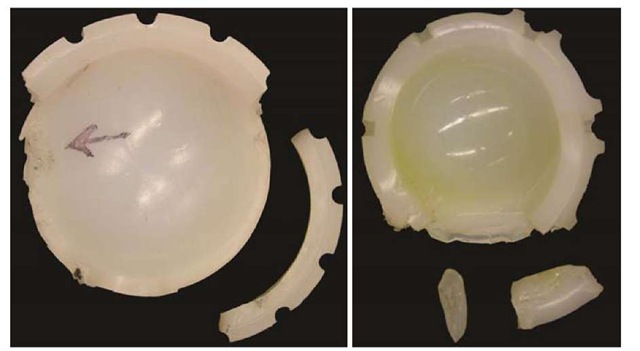
Cross-linked ultrahigh molecular weight polyethylene (UHMWPE) has seen increasing use as a compliant bearing material in total joint replacements (e.g., artificial knees and hips). While a highly cross-linked UHMWPE can experience volumetric wear less than 20% of that for conventional (uncross-linked) formulations in a wear simulator [1], the resistance to crack propagation concomitantly is deleteriously reduced by 50% [2, 3]. This increased wear resistance is of great importance to the clinical community, as microscopic UHMWPE wear debris in the joint capsule have been linked to a runaway immune response termed wear-mediated osteolysis [3], which ultimately can result in large defects in the surrounding bone and failure of the implant. Thus, cross-linked UHMWPE is widely used for its wear resistant properties, despite it being more susceptible to crack propagation and fracture. While all of the structural implications of this trade-off have not yet been elucidated, recent reports of the clinical fracture of cross-linked UHMWPE total hip replacement components demonstrate their susceptibility to crack initiation and propagation near a notch under typical service conditions (Fig.1) [4].
Fig.1 Two cross-linked UHMWPE total hip replacement bearings that fractured in patients under ordinary service conditions.
Thus, it is clear that the material resistance of various grades of UHMWPE to crack initiation and propagation in a notch-affected region is of particular interest. Unfortunately, the fatigue and fracture behavior of UHMWPE and remains only marginally understood; the purpose of this work is to elucidate the intrinsic failure of these materials and provide a clear failure criterion for evaluating the structural suitability of a given formulation of UHMWPE in a particular component design.
The crack propagation behavior of UHMWPE has been shown to behave in a static (non-cyclic) mode, i.e., predictable from quasi-static experiments, with no true cyclic damage mechanism [5, 6], i.e., the average crack propagation velocity in a variety of cyclically loaded correlates to the maximum of the waveform, independent of mean stress, stress range, waveform-specific effects, or frequency effects.
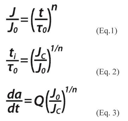
Static mode fatigue behavior is expected for a viscous solid, where relaxation processes ahead of a crack tip dominate the deformation and energy dissipation phenomena in the fracture process zone. A mathematical model due to J.G. Williams predicts crack propagation velocity (da/dt) and time to crack initiation (t), related to the rate of energy accumulation near the crack tip under static loading (Eqs.1-3) [7].
This model employs a power-law increasing J with exponent n (often, but not necessarily, derived from a time power-law increasing material compliance), time constant r0, and instantaneous J-integral J0 (Eq.1), and an exponent n which roughly is seen to govern the overall severity of the viscous response. The behavior described by this model for a notched component is schematized in Fig.2 for a typical ramp-and-hold load controlled experiment.
Fig.2 Schematic of Williams time-dependent J on log-log axes. An initial load ramp applied to a notch increases J to J0, after which the load is held and J increases according to a power-law with exponent n. Ultimately J reaches Jc, the threshold for crack initiation, and the crack begins to propagate at an approximately constant J.
When the J-integral (under a static load) eventually reaches the value necessary for crack initiation, Jc, Eq.1 can be manipulated to give the time to crack initiation, tb It can also be shown (Eq.3) that the subsequent crack propagation velocity depends on the initially applied J in a similar power law, with a scaling coefficient Q which is itself a function of the compliance, cohesive stress, and toughness. The exponential factor n unifies Eqs. 1-3 and ties them to the viscous J response, providing a means of predicting the fatigue performance of a material based on its dynamic constitutive behavior.
Mechanistically-motivated constitutive modeling of UHMWPE has produced numerical results that reproduce its hyperelastic-viscoplastic material behavior in wide variety of loading and boundary configurations [8-10]. The Hybrid Model [9] and Three Network Model (TNM) [11] are two very promising constitutive models for UHMWPE that combine hyperelastic rubber-elastic responses with power law viscoplastic behavior representing amorphous chain disentanglement and crystal plasticity, in addition to a hardening response for the crystal plasticity. Both models predict the average molecular chain strain (sch) in the amorphous polymer phase, which is related to the average of the trace of the right stretch tensor (Eq.4),
and has been shown to predict tensile rupture in UHMWPE better and more generally than typical engineering failure criteria [10]. This factor does not appear in the Williams analytical model, but serves as an additional quantity of interest for predicting the local failure of material near a notch root or crack tip.
In this work we conducted constant load crack initiation and propagation experiments on pre-notched compact tension specimens, and simulated the same experiment using FEA with the TNM constitutive model calibrated to three different uniaxial tensile experiments. We hypothesized that, in a notched UHMWPE specimen, the initiation time (t) and crack propagation velocity (da/dt) under static loading are driven by the viscoplastic dynamic response of the material, and thus UHMWPE crack behavior can be predicted by an appropriately calibrated viscoplastic FEA model. It was also hypothesized that a critical value of J and 8ch each would correlate with crack initiation in UHMWPE.
Materials and Methods
Ram extruded rods of GUR 1050 UHMWPE resin were gamma irradiated with a dose of 65 kGy and subsequently remelted (Orthoplastics, Lancashire, UK), and were machined into notched round compact tension (CT) and waisted cylindrical tensile test specimens. The CT specimens had a crack length a=17 mm, length W=40 mm, thickness B=20 mm, and notch root radius R=0.25 mm. Three tests were run to failure under a static load of either 900 N, 800 N, or 750 N on an Instron servohydraulic frame. Crack propagation was recorded with a travelling microscope. Crack advance was reported as loss of ligament length (remaining material ahead of crack tip; a-W) to account for gross motion of the crack tip during the test. Ligament reduction was assumed to be due to both gross specimen creep and true crack growth.
Tensile specimens had a gage diameter of D=7.67 mm and a gage length L=14 mm. One specimen was taken to failure at a monotonically increasing displacement of 30 mm/min. Two other specimens were tested in a creep mode with a constant engineering stress of either 14 or 20 MPa, which were respectively chosen to be moderately or marginally below the instantaneous yield stress of approximately 22 MPa. A video extensometer (Instron, Norwood, MA) recorded true strain throughout the tests.
CT specimen deformation was numerically modeled with two-dimensional plane stress finite element analyses (FEA) in ABAQUS CAE 6.8 (Simulia, Providence, RI). The model consisted of 2450 8-node quad elements (CPS8R), with a strongly biased mesh (crack tip element 4×4 ^m, Fig.3). No element failure was modeled, and so the FEA analysis was undertaken to understand the material behavior in the specimen prior to the instant of material failure at the crack tip.
Fig.3 Deformed FEA mesh; whole model (a) and detail view of crack tip (b)
The load was applied as a distributed pressure, linearly ramped over 0.1 s, on the horizontally constrained specimen pin holes. We employed the TNM constitutive model as a user material subroutine (Veryst, Cambridge, MA). The model parameters were iteratively fit simultaneously to the three sets of experimental monotonic and creep data until agreement with each test was achieved. The FEA was used to predict the creep-related ligament reduction, J-integral, and molecular chain strain (sch) at the notch root. J showed moderate path-dependence near the crack tip, so J was defined as the mean of the first 10 integration contours.
Results
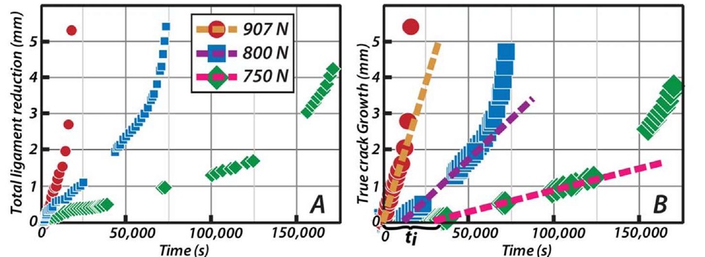
The 800 N and 750 N tests both clearly showed logarithmic initial ligament reduction prior to crack initiation, consistent with FEA creep predictions (below). The ligament reduction data then transitioned to an approximately linear stable growth region followed by instability and failure (Fig.4a). True crack growth was determined by regression fitting the initial logarithmic specimen creep component of the ligament reduction and subtracting it from the total ligament reduction at all times (Fig.1B). Constant velocity crack growth initiated at a time ti, before which true crack growth was negligible (Fig.4b, Table 1). The U for 907 N was difficult to confidently extract; hence, related values in Table 1 are estimates.
Fig.4 a) Total ligament reduction in CT tests, showing an initial specimen creep-dominated logarithmic response, followed by approximately 2 mm of stable growth, then instability. b) True crack growth, i.e., logarithmic creep contribution subtracted ligament reduction, with constant velocity regression shown. Note ti for each, before which true crack growth is negligible.
The TNM model was successfully calibrated simultaneously to the monotonic and creep experiments (Fig.5). The creep results transition from small-strain creep, through a viscoplastic yield transition up to an asymptotic strain plateau (without failure). Similar large strain yield and creep behavior has been reported elsewhere for UHMWPE [12]. From a constitutive behavior perspective, accurately modeling the stress-dependent rate of yield and the subsequent strain asymptote are critical for an accurate representation of the viscous deformation in the highly stressed region near a notch or crack tip. Short times were not calibrated in the creep tests due to minimum time step limitations, but short time responses were accurately probed in the monotonic experiment. Thus, multiple orders of magnitude of time, strain rate, and strain were calibrated between the three tensile experiments.
Fig.5 Experimental and FEA predicted behavior using calibrated TNM for a) monotonic uniaxial tension to failure, and b) creep at 20 and 14 MPa (engr. stress). Note the distributed yield transition in the creep results.
FEA predicted a J-integral with a power law time-dependence, satisfying Eq.1 with exponent n: nFEA=0.15, and a logarithmically increasing ech at the notch root (Fig.6). The model also predicted a logarithmic gross ligament reduction prior to crack initiation, thus supporting the subtraction of that portion of the experimental results to obtain true crack growth (i.e., Fig.4b). The experimentally determined ti’s (Fig.6) can be plotted on the FEA results, and these map to for each predicted response to a single FEA predicted value of J and 8ch at crack initiation (respectively denoted, J(ti) and 8ch(ti)). Thus, J(ti) and sch(ti) both appear to represent single-valid failure criteria for crack initiation, and also appear to be in one-to-one correspondence.
Fig.6 FEA predictions of (a) J-integral and (b) average molecular chain strain. Superimposed on the numerical predictions are the experimentally observed crack initiation times (ti), which in each case map to a single value of the predicted parameter for all three tests, supporting the notion of J and ech as failure criteria.
Discussion
The experimental crack initiation and propagation results match the expected response, i.e., a delayed initiation event followed by a constant crack velocity for a constant applied load, and ultimately instability and failure. The delayed initiation time was extracted by fitting subtracting the initial logarithmic response for all time, which the FEA predicted was due to whole specimen creep prior to crack initiation.
An estimate of the experimental value of the exponential factor n can be obtained by taking the ratio of either Eq.2 or Eq.3 from the experimental values of ti or da/dt, while assuming the applied J-integral to be proportional to the square of the applied load (this is expected from fracture mechanics and was confirmed with FEA). When this is done, the prefactor Q drops out, since it is related to material properties that are constant in this case, as does the time constant. The resulting values of the exponent are termed nEQ2 and nEQ3, and are listed in Table 1. These experimental estimates of the exponent n agree well with that predicted by the FEA, which indicates that the viscoplasticity effects in the mathematical and numerical analysis match with one another. Agreement in the exponent n links the analytical, experimental, and numerical components of this work, and strongly motivates the contention that the viscoplastic material behavior drives crack initiation and propagation phenomena in UHMWPE.
The results for J are generally applicable to design of arbitrarily shaped components with stress concentrations, via traditional arguments of similarity employed in fracture analyses. Likewise, sch is a locally calculated invariant parameter, and has no direct dependence on the boundary conditions far from the crack tip, and therefore can be abstracted and used in the analysis of engineered components. However, both J and sch have limitations to their interpretation; J is path-dependent and does not correspond to an intrinsic local material state, sch is an empirical simplification of the stretch tensor and does not have a rigorous link to the local terminal behavior of the molecules in the amorphous phase of the polymer. The fact that they both correlate to crack initiation, while nevertheless representing such different quantities in fracture mechanics, strengthens the case for each as a failure criterion for prediction of crack initiation from notch roots. In this regard, sch may have an advantage in future analyses, where a critical value can be used to trigger element deletion and model crack growth. In such a scenario, J can be used as a check to ensure that crack initiation triggers at the appropriate state and proceeds at the approximately constant value predicted by the analytical model.
It is worth mentioning that Eq.2 contains not just intrinsic material information relevant to incipient crack formation (through Jc, n, and r0), but also extrinsic information related to the boundary conditions and design (through J0). When designing components, engineers often have to play extrinsic constraints on the design against material selection decisions, and to balance these trade-offs to produce a safe and efficacious final product. When no clear link can be made between failure phenomena and such extrinsic factors, it can be difficult to predict the performance of the final design with confidence. A clear case in point is the failures shown in Fig.1, where the designed geometry was inherited from a previous design that had employed an uncross-linked UHMWPE, and cross-linked UHMWPE was substituted in the absence of a clear design rule regarding the danger of substituting a material with inferior fracture resistance in designs with stress-concentrating features [4]. This work was motivated in large part by the lack of such a design rule guiding the trade-off of design and material features, and Eq.2 represents an easily applicable method to achieve this in fracture mitigation. Furthermore, having a direct way to accommodate these trade-off decisions allows design engineers the freedom to achieve a given level of performance without restriction on whether it is accomplished by material substitution, redesign to reduce stress concentration or far-field stress (J0), or some combination of these tactics.


