A video sequence is in principle a sequence of images. The methods presented in the previous topics therefore apply equally well to a video sequence as an image. We simply process one image at a time. There are, however, two differences between a video sequence and an image. First, working with video allows us to consider temporal information and hence segment objects based on their motion. This is discussed below in Sect. 8.2. Moreover, temporal information is the cornerstone of tracking, which is described in the next topic. Second, video acquisition and image acquisition may not be the same, and that can have some consequences. Below, this is discussed.
Video Acquisition
A video camera is said to have a certain framerate. The framerate is a measure for how many images the camera can capture per second and is measured in Hertz (Hz). The framerate depends on the number of pixels (and the number of bits per pixel) and the electronics of the camera. Usually the framerate is geared toward a certain transmission standard like USB, Firewire, Camera Link, etc. Each of these standards has a certain bandwidth, which is the amount of data that can be transmitted per second. With a fixed bandwidth we are left with a choice between high resolution of the image and a high framerate. When one goes up the other one goes down. In the end the desired framerate and resolution will always depend on the concrete application.
Say we have a system including a camera with a framerate of 20 Hz. This means that a new image is captured every 50 ms. But it also means that the image processing algorithms can spend a maximum of 50 ms per image. To underline this we often talk about two framerates; one for the camera and one for the image processing algorithms. The overall framerate of a system is the smallest of the two framerates.
Another important factor in video acquisition is compression. Very often the captured video sequence needs to be compressed in order to insure a reasonable framerate/resolution. The more the video is compressed, the higher the framer-ate/resolution, but the worse the quality of the decompressed video. The question is of course if the quality lose associated with video compression is a problem in a particular application or not? To be able to answer this we first need to understand what compression is, see Fig. 8.1.
Fig. 8.1 Compression and decompression of video
Overall there exist two different types of compression; lossy and lossless. In the latter type the captured video in the camera and the decompressed video on the computer is exactly the same. This is virtually never used and hence not described further. In the former type of compression some information will be lost. Many different lossy video compression algorithms exist, but they all have a similar core. First of all they are developed with focus on the human mind in the sense that if a human looks at the captured video and the decompressed video, the difference should be as small as possible. That is, the information lost in video compression is optimized with respect to the human visual perception capabilities, i.e., a human will not notice the missing information. This may not be optimal from a computer’s point of view, in the sense that the information lost in the compression can affect the image processing algorithms, but this is just how it is.
Humans are more sensitive to changes in the lighting than changes in the colors. The YCbCr color representation is therefore used, see Sect. 3.3.3, and the Cb and Cr components are compressed harder than the Y component. Another aspect of human perception involved in compression of video is the fact that humans are better at seeing gradual changes in an image as opposed to rapid changes. This fact is utilized by transforming the image into a new representation where the level of change is apparent. Rapid changes are then compressed harder than gradual changes.
Another main ingredient in video compression is to exploit that consecutive images usually do not change very much. To exploit this the image is first divided into a number of blocks. Each block is then used as a template to search for a matching block in the previous image. Template matching is used for this purpose, see Sect. 5.2.1. The two blocks are now subtracted and their difference is usually small and hence can be represented by fewer bits than the original block. This is done for all blocks in the input. The last component in video compression is similar to what is used for image, sound and text compression, namely entropy coding. This covers lossless methods that can compress based on the statistical nature of the data. For example, say we have the following pixel values:
2, 3, 3, 3, 3, 3, 3, 3, 67,12,12,12,12,10. Using entropy coding this can be written as 2, 3, 255, 6, 67,12, 255, 3,10, where 255 indicates that the next value states the number of repetitions, that is: 3, 255, 6 = 3, 3, 3, 3, 3, 3, 3. Originally we had 14 values and now we only have nine values, i.e., a compression factor of 14/9 = 1.56.
Fig. 8.2 Different blocking effects illustrated in a zoomed picture in order to increase visibility
How many bits needed to represent a compressed image in the video sequence depends on the content of the video. Sometimes we require more bits than are available in the bandwidth. This means that the compression method will have to delete some additional information, for example by a harder compression of the colors or by simply ignoring details of one or more blocks. The consequence of the latter can be that one or more blocks in the decompressed image contain less detail and hence appear blurry or do not contain any detail at all, i.e., will be black. Such phenomena are known as blocking artifacts and a few are illustrated in Fig. 8.2.
The point of all the above is that you as a designer need to look into these issues before doing video processing. It might be better to spend some extra money on a good camera (and transmission) producing good data compared to spending lots of time (in vain?) trying to compensate for poor data with clever algorithms. This is especially true if developing a system based on color processing. A compromise can be to use a cheap camera with poor quality video and then try to detect if blocking has occurred and if so delete such images from the video sequence.
No matter the type of camera and compression algorithm, the captured video sequence may contain motion blur due to motion in the scene, see Sect. 2.2. A similar problem is that the depth-of-field may not cover the entire FOV and hence moving objects may be blurred due to an incorrect focus. Processing video containing blur will possibly affect the results and should therefore be avoided is possible. One approach for doing so is to analyze each image and try to measure the level of blur. If too blurry the image should be deleted. The consequence of a blurred image is that the magnitudes of the edges in the image are small. So the blurriness can be measured by analyzing the edges in the image, see Sect. 9.3.1. Another approach is to compare the input image with a blurred version of the input image. If the input image contains a lot of edges, i.e., is sharp, then the two images will be significantly different. If they are similar it is likely that the input image was blurred in the first place.
Detecting Changes in the Video
In many systems we are interested in detecting what has changed in the scene, i.e., a new object enters the scene or an object is moving in the scene. For such purposes we can use image subtraction, see Chap. 4, to compare the current image with a previous image. If they differ, the difference defines the object or movement we are looking for. In the rest of this topic we will elaborate on this idea and present an approach for detecting changes in video data.
The Algorithm
The algorithm for detecting changes in a video sequence consists of five steps:
1. Save reference image
2. Capture current image
3. Perform image subtraction
4. Thresholding
5. Filter noise
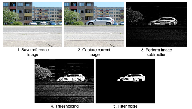
The algorithm can be performed in two different ways depending on the goal and assumptions. If the background in the scene can be assumed to be static then every new object entering the scene can in theory be segmented by subtracting an image of the background from the current image. This process is denoted background subtraction and illustrated in Fig. 8.3. The reference image of the background is captured as the first image when the system commences.
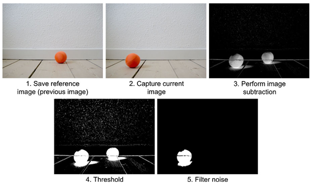
The other way the algorithm can be performed is when the assumption of a static background breaks down. For example if the light in the scene changes significantly, then an incoming image will be very different from the background even though no changes occurred in the scene. In such situations the reference image should be the previous image. The rationale is that the background in two consecutive images from a video sequence is probably very similar and the only difference is the new/moving object, see Fig. 8.4. Such methods are denoted image differencing.
The difference between the two ways the algorithm can be performed results in two different types of reference image: either the first in a sequence or the previous image. The remaining four steps in the algorithm are the same for the two algorithms and performed for each new image in the video.
Step Three
In Step three of the algorithm the reference image and current image are subtracted. Let us denote the reference image r(x,y) and the current image f(x,y). The resulting image, g(x,y), is then given as ![]()
Fig. 8.3 The five steps of segmenting video data through background subtraction
In Fig. 8.3 step three is shown. The car stands out in the resulting image since the pixel values of the car are different from the pixel values of the reference image. However, at some locations where a pixel in the reference image has a similar value to the pixel at the current image the resulting pixel value will be close to zero and hence will not stand out. This can for example be seen around the wheels of the car. As a designer you therefore need to introduce a background which is as different as possible from the object you intend to segment. For example, choosing a black background when segmenting white balls is a very good idea, whereas a white background is obviously not.
Another issue regarding image subtraction, is that negative values are very likely to appear in the resulting image g(x, y). Say that your task is to segment objects when they pass by your camera. The objects are black and white, meaning that they have pixel values which are either black, f(x, y) = 0, or white f(x, y) = 255. You then design a gray background which has intensity values around 100, i.e., r(x, y) = 100, and perform image subtraction:
A common error is to set a negative pixel to zero. If this is done then only the white parts of the object is detected. Note that whether g(x, y) = 155 or g(x, y) = -155 is equally important. The correct solution is to apply the absolute value of g(x, y), Abs(g(x, y)).
Fig. 8.4 The five steps of segmenting video data through image differencing
Step Four
Step four of the algorithm is simply a matter of binarizing the difference image Abs(g(x, y)) by comparing each pixel with a threshold value, T:
Step Five
The threshold in step four will, like any other threshold operation, produce noise due to an imperfect camera sensor, small fluctuations in the lighting, the object being similar to the background, etc. The noise will be in the form of missing pixels inside the silhouette of the object and silhouette-pixels outside the actual silhouette (false positives). See Figs. 8.3 or 8.4 for examples.
The noise will in general have a negative influence on the quality of the results and step five therefore removes the noise (if possible) using some kind of filtering. Small isolated silhouette-pixels outside the actual silhouette can often be removed using either a median filter or a morphologic opening operation. The holes inside the silhouette can often be removed using a morphologic closing operation. Which method to apply obviously depends on the concrete application.
In the following, image differencing and background subtraction are explained in more detail.
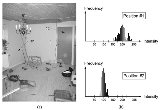
Fig. 8.5 (a) A static background image. The two arrows indicate the position of two pixels. (b) Histograms of the pixel values at the two positions. The data come from a sequence of images


