The RGB Color Space
According to Eq. 3.1a color pixel has three values and can therefore be represented as one point in a 3D space spanned by the three colors. If we say that each color is represented by 8-bits, then we can construct the so-called RGB color cube, see Fig. 3.7.
In the color cube a color pixel is one point or rather a vector from (0, 0,0) to the pixel value. The different corners in the color cube represent some of the pure colors and are listed in Table 3.2. The vector from (0, 0, 0) to (255,255,255) passes through all the gray-scale values and is denoted the gray-vector. Note that the gray-vector is identical to Fig. 3.2.
Converting from RGB to Gray-Scale
Even though you use a color camera it might be sufficient for your algorithm to apply the intensity information in the image and you therefore need to convert the color image into a gray-scale image. Converting from RGB to gray-scale is performed as
where I is the intensity and Wr, Wg, and Wb are weight factors for R, G, and B, respectively.
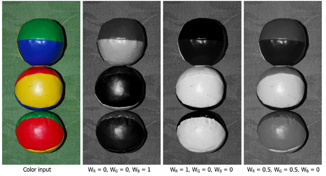
Fig. 3.8 A color image and how it can be mapped to different gray-scale images depending on the weights
To ensure the value of Eq. 3.3 is within one byte, i.e. in the range [0,255], the weight factors must sum to one. Thatis Wr + Wg + Wb = 1. As default the three colors are equally important, hence Wr = Wg = Wb = 1, but depending on the application one or two colors might be more important and the weight factors should be set accordingly. For example when processing images of vegetation the green color typically contains the most information or when processing images of metal objects the most information is typically located in the blue pixels. Yet another example could be when looking for human skin (face and hands) which has a reddish color. In general, the weights should be set according to your application and a good way of assessing this is by looking at the histograms of each color.1 An example of a color image transformed into a gray-scale image can be seen in Fig. 3.8. Generally, it is not possible to convert a gray-scale image back into the original color image, since the color information is lost during the color to gray-scale transformation.
When the goal of a conversion from color to gray-scale is not to prepare the image for processing but rather for visualization purposes, then an understanding of the human visual perception can help decide the weight factors. The optimal weights vary from individual to individual, but the weights listed below are a good compromise, agreed upon by major international standardization organizations within TV and image/video coding. When the weights are optimized for the human visual system, the resulting gray-scale value is denoted luminance and usually represented as Y.
Fig. 3.9 The RGB color cube. Each dot corresponds to a particular pixel value. Multiple dots on the same line all have the same color, but different levels of illumination
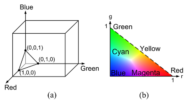
Fig. 3.10 (a) The triangle where all color vectors pass through. The value of a point on the triangle is defined using normalized RGB coordinates. (b) The chromaticity plane
The Normalized RGB Color Representation
If we have the following three RGB pixel values (0, 50,0), (0,100,0), and (0, 223, 0) in the RGB color cube, we can see that they all lie on the same vector, namely the one spanned by (0,0,0) and (0,255,0). We say that all values are a shade of green and go even further and say that they all have the same color (green), but different levels of illumination. This also applies to the rest of the color cube. For example, the points (40, 20, 50), (100, 50,125) and (200,100,250) all lie on the same vector and therefore have the same color, but just different illumination levels. This is illustrated in Fig. 3.9.
If we generalize this idea of different points on the same line having the same color, then we can see that all possible lines pass through the triangle defined by the points (1,0,0), (0, 1, 0) and (0,0,1), see Fig. 3.10(a). The actual point (r, g,b) where a line intersects the triangle is found as2:
These values are named normalized RGB and denoted (r, g,b). In Table 3.3 the rgb values of some RGB values are shown. Note that each value is in the interval [0,1] and that r + g + b = 1. This means that if we know two of the normalized RGB values, then we can easily find the remaining value, or in other words, we can represent a normalized RGB color using just two of the values. Say we choose r and g, then this corresponds to representing the triangle in Fig. 3.10(a) by the triangle to the right, see Fig. 3.10(b). This triangle is denoted the chromaticity plane and the colors along the edges of the triangle are the so-called pure colors. The further away from the edges the less pure the color and ultimately the center of the triangle has no color at all and is a shade of gray. It can be stated that the closer to the center a color is, the more “polluted” a pure color is by white light.
Summing up we can now re-represent an RGB value by its “true” color, r and g, and the amount of light (intensity or energy or illumination) in the pixel. That is,
where![tmp26dc-57_thumb[2] tmp26dc-57_thumb[2]](http://what-when-how.com/wp-content/uploads/2012/07/tmp26dc57_thumb2_thumb.png) In Table 3.3 the rgI values of some RGB values are shown.3
In Table 3.3 the rgI values of some RGB values are shown.3
Separating the color and the intensity like this can be a powerful notion in many applications. In Sect. 4.4.1 one will be presented.
In terms of programming the conversion from (R,G, B) to (r, g, I) can be implemented in C-Code as illustrated below:
where M is the height of the image, N is the width of the image, input is the RGB image, and output is the rgI image. The programming example primarily consists of two FOR-loops which go through the image, pixel-by-pixel, and convert from an input image (RGB) to an output image (rgI). The opposite conversion from (r, g,I) to (R,G,B) can be implemented as
where M is the height of the image, N is the width of the image, input is the rgI image, and output is the RGB image.
![tmp26dc-50_thumb[2] tmp26dc-50_thumb[2]](http://what-when-how.com/wp-content/uploads/2012/07/tmp26dc50_thumb2_thumb.png)


![tmp26dc-55_thumb[2] tmp26dc-55_thumb[2]](http://what-when-how.com/wp-content/uploads/2012/07/tmp26dc55_thumb2_thumb.png)
![tmp26dc-59_thumb[2] tmp26dc-59_thumb[2]](http://what-when-how.com/wp-content/uploads/2012/07/tmp26dc59_thumb2_thumb.png)
![tmp26dc-60_thumb[2] tmp26dc-60_thumb[2]](http://what-when-how.com/wp-content/uploads/2012/07/tmp26dc60_thumb2_thumb.png)
