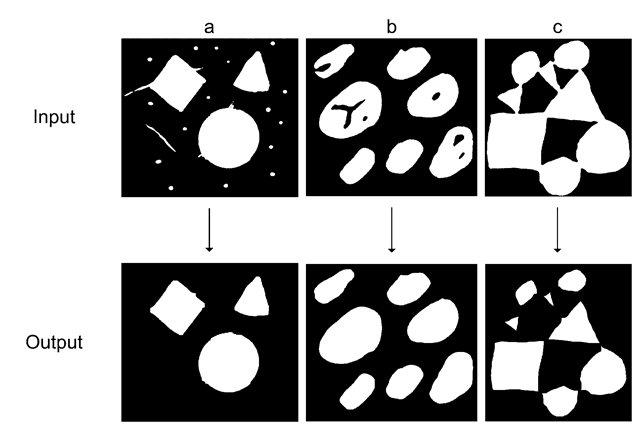
One important branch of neighborhood processing is mathematical morphology— or simply morphology. It is applicable to both gray-scale images as well as binary images, but in this text only operations related to binary images are covered. Morphology on binary images has a number of applications and in Fig. 6.1 three typical ones are illustrated. The first two illustrate how to remove the noise that very often is a side effect of thresholding. It is next to impossible to achieve a perfect binary image using thresholding. We are very likely to under-segmentation in some regions and over-segmentation in other regions. The leftmost figure illustrates oversegmentation in the form of the small objects in the image. Under-segmentation is illustrated in the middle figure as holes inside the object. The problems associated with thresholding were also mentioned in Chap. 4 where it could be seen as the problematic histogram in Fig. 4.17.
The rightmost example in Fig. 6.1 illustrates a problem which is related to the next topic, where we will start to analyze individual objects. To this end we need to ensure that the objects are separated from each other.
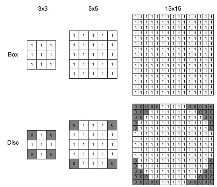
Morphology operates like the other neighborhood processing methods by applying a kernel to each pixel in the input. In morphology, the kernel is denoted a structuring element and contains ‘0’s and ‘1’s. You can design the structuring element as you please, but normally the pattern of ‘1’s form a box or a disk. In Fig. 6.2 different sized structuring elements are visualized. Which type and size to use is up to the designer, but in general a box-shaped structuring element tends to preserve sharp object corners, whereas a disk-shaped structuring element tends to round the corners of the objects.
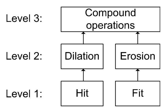
A structuring element is not applied in the same way as we saw in the previous topic for the kernels. Instead of using multiplications and additions in the calculations, a structuring element is applied using either a Hit or a Fit operation. Applying one of these operations to each pixel in an image is denoted Dilation and Erosion, respectively. Combining these two methods can result in powerful image processing tools known as Compound Operations. We can say that there exist three levels of operation, see Fig. 6.3, and in the following, these three levels will be described one at a time. Note that for simplicity, we will in this topic represent white as 1 instead of 255.
Fig. 6.1 Three examples of the uses of morphology.
(a) Removing small objects.
(b) Filling holes. (c) Isolating objects
Fig. 6.2 Two types of structuring elements at different sizes
Level 1: Hit and Fit
The structuring element is placed on top of the image as was the case for the kernels in the previous topic. The center of the structuring element is placed at the position of the pixel in focus and it is the value of this pixel that will be calculated by applying the structuring element. After having placed the structuring element we can apply one of two methods: Hit or Fit.
Fig. 6.3 The three levels of operation involved in Morphology
Hit
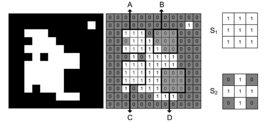
For each ‘1’ in the structuring element we investigate whether the pixel at the same position in the image is also a ‘1’. If this is the case for just one of the ‘1’s in the structuring element we say that the structuring element hits the image at the pixel position in question (the one on which the structuring element is centered). This pixel is therefore set to ‘1’ in the output image. Otherwise it is set to ‘0’. In Fig. 6.4 and Table 6.1 the hit operation is illustrated with two different structuring elements.
Fit
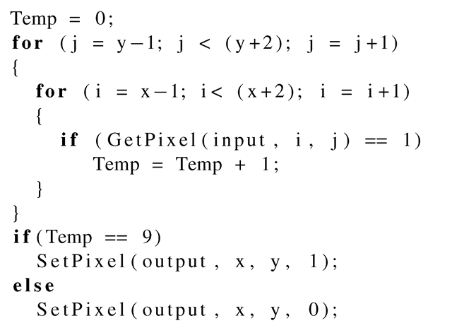
For each ‘1’ in the structuring element we investigate whether the pixel at the same position in the image is also a ‘1’. If this is the case for all the ‘1’s in the structuring element we say that the structuring element fits the image at the pixel position in question (the one on which the structuring element is centered). This pixel is therefore set to ‘1’ in the output image. Otherwise it is set to ‘0’. In Fig. 6.4 and Table 6.1 the fit operation is illustrated with two different structuring elements. Below we show C-code for the fit operation using a 3 x 3 box-shaped structuring element:
where (x, y) is the position of the pixel being processed.
Fig. 6.4 A binary image illustrated both by colors (black and white) and numbers (0 and 1). A, B, C and D illustrate four 3 x 3 image regions centered at: A: f(3, 3), B: f(7, 3), C: f(3, 7) and D: f(8, 8). Lastly two different 3 x 3 structuring elements are illustrated
|
Position |
SE |
Fit |
Hit |
|
A |
S1 |
No |
Yes |
|
A |
Si |
No |
Yes |
|
B |
S1 |
No |
Yes |
|
B |
Si |
No |
No |
|
C |
S1 |
Yes |
Yes |
|
C |
Si |
Yes |
Yes |
|
D |
S1 |
No |
No |
|
D |
Si |
No |
No |
Table 6.1 Resultsof applying the two structuring elements (SE) in Fig. 6.4 to the input image in Fig. 6.4 at four positions: A, B, C, and D
Level 2: Dilation and Erosion
At the next level Hit or Fit is applied to every single pixel by scanning through the image as shown in Fig. 4.28. The size of the structuring element in these operations has the same importance as the kernel size did in the previous topic. The bigger the structuring element, the bigger the effect in the image. As described in the previous topic we also have the border problem present here and solution strategies similar to those listed in Sect. 5.1 can be followed. For simplicity we will ignore the border problem in this topic.
Dilation
Applying Hit to an entire image is denoted Dilation and is written as
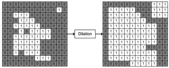
Fig. 6.5 Dilation of the binary image in Fig. 6.4 using S
The term dilation refers to the fact that the object in the binary image is increased in size. In general, dilating an image results in objects becoming bigger, small holes being filled, and objects being merged. How big the effect is depends on the size of the structuring element. It should be noticed that a large structuring element can be implemented by iteratively applying a smaller structuring element. This makes sense since Eq. 6.2 holds. The equation states that dilating twice with SE1 is similar to dilating one time with SE2, where SE2 is the same type but has twice the radius of SE1. For example, if SE2 is a 5 x 5 structuring element, then SE1 is a 3 x 3, etc.
In Fig. 6.5 the binary image in Fig. 6.4 is dilated using the structuring element S1. First of all we can see that the object gets bigger. Secondly we can observe that the hole and the convex parts of the object are filled, which makes the object more compact.
In Fig. 6.6 a real image is dilated with different sized box-shaped structuring elements. Again we can see that the object is becoming bigger and that holes inside the person are filled. What is, however, also apparent is that the noisy small objects are also enlarged. Below we will return to this problem.
Erosion
Applying Fit to an entire image is denoted Erosion and is written as
The term erosion refers to the fact that the object in the binary image is decreased in size. In general, erosion of an image results in objects becoming smaller, small objects disappearing, and larger objects splitting into smaller objects. As for dilation the effect depends on the size of the structuring element and large structuring elements can be implemented using an equation similar to Eq. 6.2.
Fig. 6.6 Dilation with different sized structuring elements
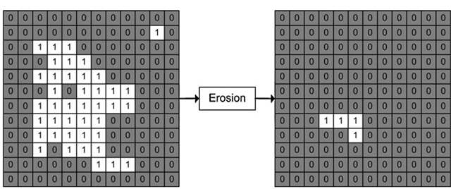
Fig. 6.7 Erosion of the binary image in Fig. 6.4 using S1
In Fig. 6.7 the binary image in Fig. 6.4 is eroded using the structuring element S1. First of all we can see that the main object gets smaller and the small objects disappear. Secondly we can observe that the fractured parts of the main object are removed and only the "core” of the object remains. The size of this core obviously depends on the size (and shape) of the structuring element.
In Fig. 6.8 a real image is eroded with different sized box-shaped structuring elements. Again we can see that the object becomes smaller and the small (noisy) objects disappear. So the price we pay for deleting the small noisy objects is that the object of interest becomes smaller and fractured. Below we will return to this problem.
