3.4
The next electric drive discussed is a single-phase, full-wave controlled rectifier. This adjustable speed drive is similar to the single-phase, half-wave controlled rectifier. As an example, this rectifier is presented to control a separately excited DC motor. The single-phase, full-wave controlled rectifier consists of four thyristors. The increase in thyristors provides for better control compared to the half-wave controlled rectifier. The obvious disadvantage of the full-wave rectifier is the increase in price because of the increase in the number of thyristor. Figure 3.4 shows a separately excited DC motor controlled by a single-phase, full-wave controlled rectifier.
There are three different modes of operation for the single-phase, full-wave controlled rectifier. The first is discontinuous conduction mode (DCM). In DCM, the current Ia reaches zero and stays at zero for a certain period of time. The next mode is continuous conduction mode (CCM). In CCM, Ia does not reach zero at any point during the period. The finial mode of operation is critically discontinuous
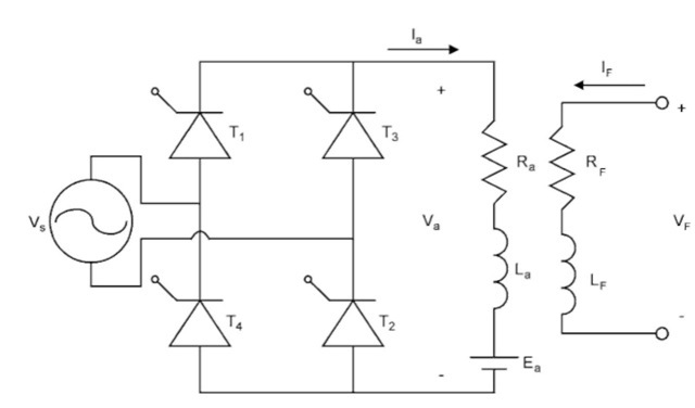
FIGURE 3.4 Single-phase, full-wave, controlled rectifier.
conduction mode (CDCM). In CDCM, the current Ia reaches zero and then immediately starts to increase.
Unlike the half-wave rectifier, the full-wave rectifier has the ability to manipulate the current when Vs is negative. There are three modes in DCM. The first mode is when from time t = 0 until a. Mode one is shown in Fig. 3.5. In mode one, there is no current in the armature; this results in a Va equal to the back emf Ea.
Mode two occurs when the source voltage Vs is positive. Mode two is shown in Fig. 3.6. In mode two, T and T2 are conducting and T3 and T4 are not conducting. Va is equal to the source voltage Vs.
The finial mode is mode three. Mode three is shown in Fig. 3.7. This mode is the opposite of mode two. In mode three, T3 and T4 are conducting and T and T2 are not conducting. This makes the voltage Va equal to the negative of the source voltage Vs.
Figure 3.8 shows the waveforms of the rectifier in DCM. As seen in Fig. 3.8, the conducting angle occurs twice per period, once when the source voltage Vs is positive and again when the source
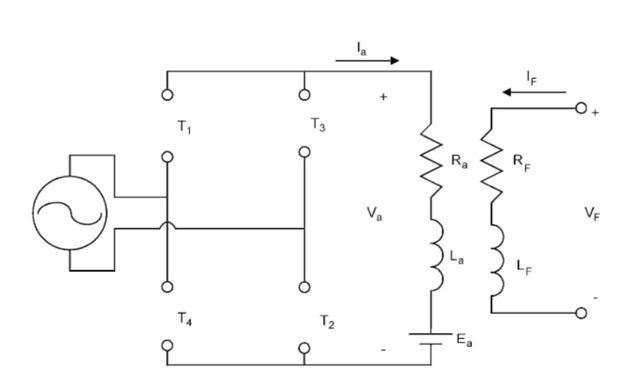
FIGURE 3.5 Mode one of DCM.
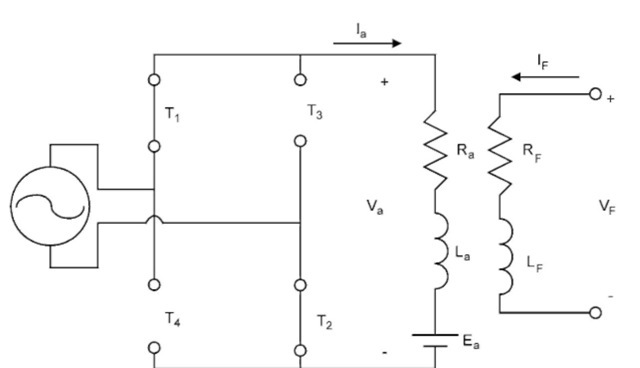
FIGURE 3.6 Mode two of DCM.
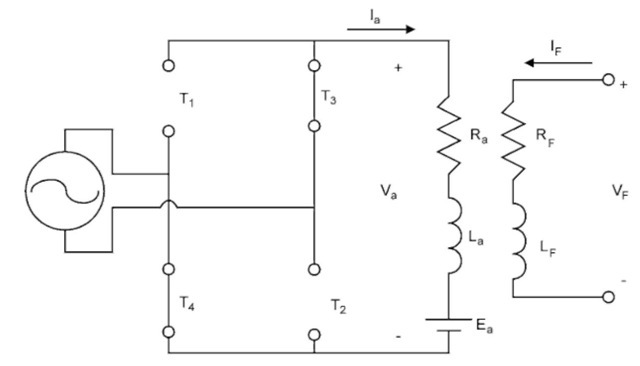
FIGURE 3.7 Mode three of DCM.
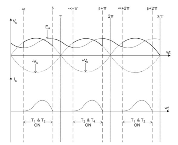
FIGURE 3.8 Waveforms of a single-phase, full-wave controlled rectifier in DCM.
voltage is negative. In addition, in mode one, the voltage Va is equal to the back EMF Ea until a.
Continuous conduction mode is similar to DCM, but in CCM mode one does not exist. Figure 3.9 shows the circuit operating in CCM. CCM occurs when Va is large compared to Ea. Notice that Va is never equal to Ea.
