3.3
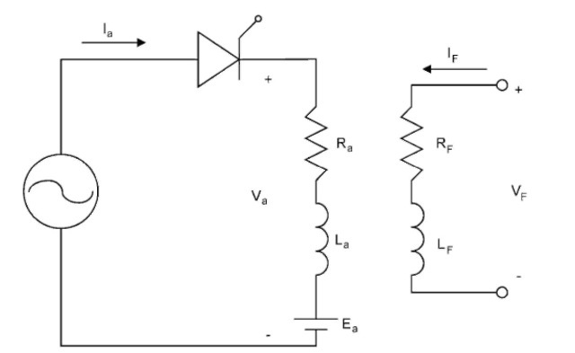
Shown in Fig. 3.2 is a separately excited DC motor controlled by a single-phase, half-wave controlled rectifier. This rectifier provides speed control for the separately excited DC motor by varying armature voltage and current.
The steady state voltage and torque equations for a separately excited DC motor are

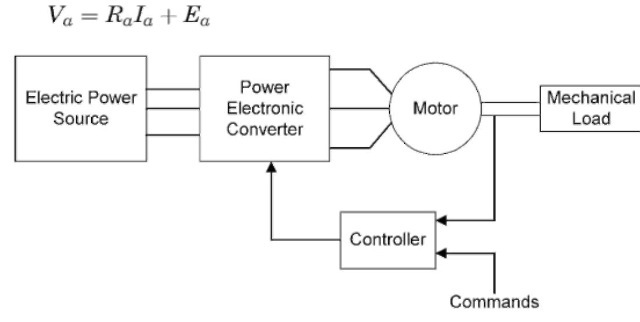
FIGURE 3.1 Block diagram of an electric motor drive.

FIGURE 3.2 Single-phase, half-wave, controlled rectifier.
![tmpBC-3_thumb[1] tmpBC-3_thumb[1]](http://lh6.ggpht.com/_X6JnoL0U4BY/S1fxRCZ-sTI/AAAAAAAAHQQ/xucE_6V_6d0/tmpBC3_thumb1_thumb.jpg?imgmax=800)
As seen from these equations, speed control can be done by varying Ra, Va, and IF. Varying Ra can only increase the speed. Also, by varying Ra, we increase the losses I2R. IF can only be decreased. This is accomplished by putting resistance in the field. Again, this increases
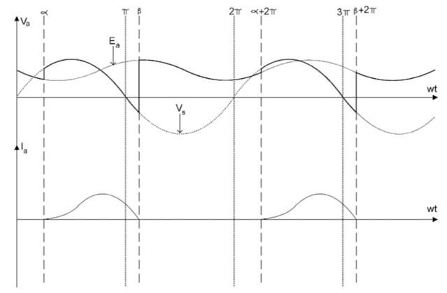
the I2R losses. Control of Vf is limited because of saturation. The best method of controlling the speed of the motor is to control Va. Using a thyristor, as shown in Fig. 3.2, the average of Va can be controlled. Figure 3.3 shows the voltage and current for a separately excited DC motor controlled by a single-phase, half-wave, controlled rectifier. As seen in Fig. 3.3, a represents the firing angle of the thyristor. This is where the thyristor turns on. Also seen in Fig. 3.3 is p. P is where the current Ia reaches zero and the thyristor turns off. From these two quantities, we define the conduction angle:
y = jS — a.
By changing the conduction angle, the average value of Va is varied. When Va is varied, the speed of the motor is changed. This is a simple but effective speed controller.

FIGURE 3.3 Voltage and current for Fig. 3.2.
SINGLE-PHASE, HALF-WAVE, CONTROLLED RECTIFIER (Electric Motor)
Next post: SINGLE-PHASE, FULL-WAVE,CONTROLLED RECTIFIER (Electric Motor)
Previous post: POWER ELECTRONIC DEVICES (Electric Motor)
