3.5
As mentioned earlier, three-phase induction motors make up the majority of the motors in the industry. This is because of their low
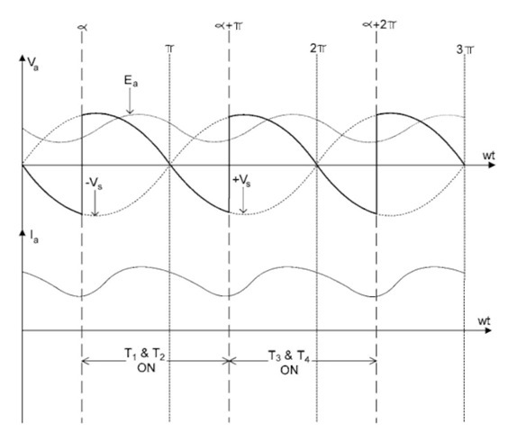
FIGURE 3.9 Waveforms of a single-phase, full-wave controlled rectifier in
CCM.
cost, low maintenance, and high efficiency. To control any motor, a strong understanding of the motor equations is needed. Before discussing the phase-controlled induction motor drives, the necessary equations are reviewed.
An induction motor is very similar to a transformer. The induction motor is an AC machine in which alternating current is supplied to the stator directly and to the rotor windings by induction, like a transformer. There are two types of induction motors: a wound-rotor induction motor and a squirrel-cage rotor induction motor. The wound rotor has slip rings mounted on the rotor shaft. These slip rings enable
the user to access the rotor winding. For steady-state operation, these windings are shorted. A squirrel-cage rotor has conducting bars embedded in slots in the rotor magnetic core. These bars are short-circuited at each end.
The synchronous speed depends on the number of pole pairs and the frequency of the source. Synchronous speed (Ns) in revolutions per second is given by
![tmpBC-11_thumb[1] tmpBC-11_thumb[1]](http://lh6.ggpht.com/_X6JnoL0U4BY/S1fyRezFiOI/AAAAAAAAHRQ/6_6P9ge0It0/tmpBC11_thumb1_thumb2.jpg?imgmax=800)
where f is the frequency of the source and P is the number of pole pairs. The difference in rotor speed N and synchronous speed Ns is represented by slip s, which is
![tmpBC-12_thumb[1] tmpBC-12_thumb[1]](http://lh6.ggpht.com/_X6JnoL0U4BY/S1fyS9EzpTI/AAAAAAAAHRY/E7004rvMWJc/tmpBC12_thumb1_thumb.jpg?imgmax=800)
At full load, slip is in the range of 2-3%. A very important characteristic of the induction motor is the speed-torque. To develop the torque equation of the induction motor the approximate equivalent circuit of an induction motor is used. Figure 3.10 shows the approximate equivalent circuit of an induction machine.
The power transferred from the stator to the rotor is called the air gap power Pg. The air gap power is the product of the torque T and the synchronous speed (Os in radians. Using the equivalent circuit, the air gap power can be represented with motor parameters. The air gap power is defined as
![tmpBC-13_thumb[1] tmpBC-13_thumb[1]](http://lh5.ggpht.com/_X6JnoL0U4BY/S1fyVRUceYI/AAAAAAAAHRg/GuKaFpPKWQ4/tmpBC13_thumb1_thumb.jpg?imgmax=800)
Mechanical power Pm is the product of torque and rotor speed O. Also using the equivalent circuit, the mechanical power can be represented using the motor parameters. Pm is represented by
![tmpBC-14_thumb[1] tmpBC-14_thumb[1]](http://lh5.ggpht.com/_X6JnoL0U4BY/S1fyWWEo7vI/AAAAAAAAHRo/-urAp0YuVhk/tmpBC14_thumb1_thumb.jpg?imgmax=800)
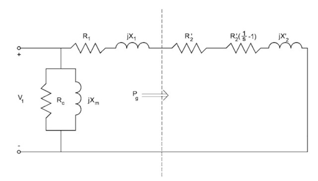
FIGURE 3.10 Approximate equivalent circuit of an induction machine.
Combining these equations, torque can be represented by
![tmpBC-16_thumb[2] tmpBC-16_thumb[2]](http://lh6.ggpht.com/_X6JnoL0U4BY/S1fyZ8FjpYI/AAAAAAAAHR4/uk9SWlbzQns/tmpBC16_thumb2_thumb.jpg?imgmax=800)
Using the equivalent circuit and the above equations, torque is represented as a function of voltage and speed:
![]()
This equation represents the torque of an induction motor as a function of voltage and speed. If the voltage is varied, the torque of the motor changes. If the frequency is varied, the speed of the motor changes.
Saturation will occur if the voltage is very large or the frequency is very low. To obtain optimal flux operation, V/f should be kept constant. This will not make the motor go into saturation.
A very simple phase-controlled induction motor is explored. To control a three-phase induction motor, an AC/AC converter can be used. Figure 3.11 shows a three-phase AC/AC converter. Notice that each phase has two thyristors. The firing angles of the thyristors in each phase are 180 degrees apart and are positioned opposite of each other. In addition, as expected, each phase is 120 degrees apart. To simplify the analysis of the phase-controlled induction motor drives, only one phase of the AC/AC converter is examined. Figure 3.12 shows phase A of the converter.
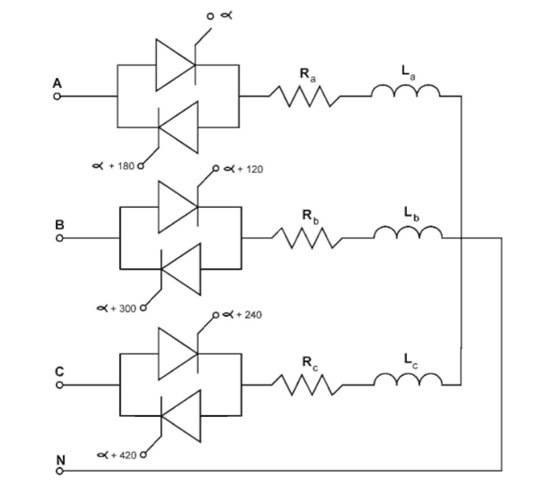
FIGURE 3.11 AC/AC converter.
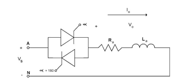
FIGURE 3.12 Phase A of the AC/AC converter.
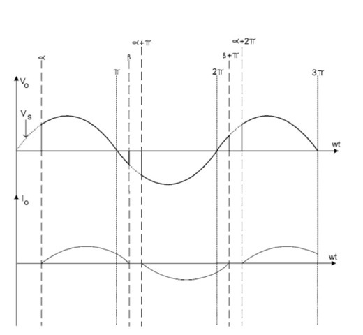
FIGURE 3.13 Waveforms of phase A of the AC/AC converter.

FIGURE 3.14 Block diagram of an advanced induction motor drive.
The waveforms of the circuit of Fig. 3.12 are shown in Fig. 3.13. This is not the most effective way of controlling an induction motor. The quality of the output voltage is not good. Furthermore, as mentioned earlier, to obtain the optimal flux operation V/f should be kept constant. Using an AC/AC converter does not keep V/f constant. A more effective induction motor drive is shown in Fig. 3.14. A constant voltage and frequency three-phase source is the input. With the AC/DC rectifier, DC/AC inverter, and controller, the voltage and frequency can be varied. The control can be used to keep V/f constant and provide optimal flux operation.
