Introduction
Every engineering decision is, by necessity, a compromise. We are not given infinite resources, either in time, money, or any physical constraints (size, weight, etc.) with which to fulfill any given requirement, and of course we must work within the bounds imposed by the basic laws of physics. Display interfaces are certainly no exception. While to this point we have been concerned primarily with examining the requirements the interface design must meet – the specifications for “getting the job done” – we now must also look at these constraints, the limitations within which the display system designer must work.
Of these, some are a bit too basic or application-specific for much attention here. The constraints of cost, physical space, and so forth will vary with each particular design, and cannot be discussed other than to note that there is generally not an unlimited amount of such resources available. Other factors entering into the interface selection include at least the following, in addition to the basic task of conveying the desired image information.
• The requirement for compatibility with existing standards or previous designs.
• Constraints imposed by regulation or law; these include such things as safety or ergonomic requirements, radiated and conducted interference limits, and similar restrictions. Note that these may be either actual legal requirements for sale of a product into a given country, region, etc. (an example might be the emissions restrictions set by the US Federal Communications Commission), or de-facto requirements set by the market itself (for example, compliance with the standards set by groups such as Underwriter’s Laboratories).
• The need to carry additional information, power, etc., over the same physical connection, and the effect these will have on the video data transmission and vice versa. An example might be a “display” connection that also carries analog audio channels, power, or supplemental digital information.
• The limits of the physical connection and media which are available and which meet the other requirements imposed on the design.
These are addressed following a review of the requirements determined by the basic image-transmission task itself.
Practical Channel Capacity Requirements
Fundamentally, the display interface’s job is the transmission of information. As such, its basic requirements can be analyzed in terms of the information capacity required of the interface, and from there to the bandwidth and noise restrictions on the physical channel or channels used to carry this information. As noted in the first topic, the amount of information required is determined by the number of samples or pixels comprising each individual image, multiplied by the rate at which these images are to be transmitted, and the number of fundamental units of information (generally expressed in terms of “bits”). For example, if we assume the usual arrays of pixels in columns and rows, with each such array considered as one “frame” of the transmission, the information rate can be no lower than:
Info, rate (bits/s) = (bits/pixel)x (pixels/line)x (lines/frame)x (frames/s)
This represents the minimum rate; in practice, the peak transmission rate required of the interface will be somewhat higher (generally by 5-50%), as there will be unavoidable periods of “dead time” (times during which no image information can be transmitted), resulting from the limitations of the display itself, the image source, or the overhead imposed by the transmission protocol.
It is very important to note that, while the above analysis seems to apply only to “digital” systems (what with the use of bits and discrete samples), information theory tells us that any transmission system may be analyzed in the same or similar manner. Transmissions which are generally labelled as “purely analog” may still be analyzed in terms of their information content and rate in “bits” and “bits/second,” through the relationships between sample rate or spatial resolution and bandwidth, and the information content of each sample (bits/sample) with such analog” concepts as dynamic range. Television provides a good example of this. The specifics of the development of the television standards of today are examined in detail later, but for now we note that the effective resolution provided by the US television standard, in the vertical direction, is roughly equivalent to 330 lines/frame. If the system is to provide equal resolving ability along both axes, the horizontal resolution should equal, in “digital” terms, approximately 440 pixels/line (given the 4:3 image aspect ratio of television). At a line rate of approximately 15.75 kHz, with roughly 80% of each line available for the actual image, this would equate to a sample rate of about 8.66 Msamples/s. As the highest fundamental frequency in a video transmission is half the sample rate (since the fastest change that can be made is from one pixel to the next and back again), this would suggest that the bandwidth required be at least 4.33 MHz, very close to the actual value used under the US standard. The number of bits required for each of these effective sample or pixels may be directly obtained from the dynamic range, which in imaging terms is equivalent to contrast.
Ignoring for the moment the problems introduced by the non-linearities of vision, the display, or the image capture system, we could simply approximate the number of bits of information per sample as the base 2 log of the dynamic range. (As there are, however, such nonlinearities in the system, any value obtained in this manner should be viewed as the absolute minimum information required per pixel, at least if linear encoding is assumed.) Through this sort of a rough calculation, we might expect to adequately convey a monochrome (“black and white”) television signal in 7-8 bits/pixel, and so we would expect to be able to convey a “TV-grade” black-and-white transmission through a channel capable of a data rate of approximately 60-70 Mbits/s.
The capacity of any real-world channel is, of course, limited. This limitation results fundamentally from two factors: the bandwidth of the channel, in the proper sense of the total range of frequencies over which signals may be transmitted without unacceptable loss, and the amount of noise which may be expected in the channel. Simply put, the bandwidth of the channel limits the rate at which the state of the signal can change, while noise limits our ability to discriminate between these states. If we are conveying information through a change of signal amplitude, for example, it does little good to define states separated by a microvolt if the noise level far exceeds this. The theoretical limit on the information capacity of any channel, regardless of its nature or the transmission protocol being used, was first expressed by Claude Shannon in his classic theorem for information capacity in a noisy, band-limited channel, as:
where BW is the bandwidth of the channel in Hz and S/N is the signal-to-noise ratio. For example, if we have a television transmission occupying 4.5 MHz of bandwidth, and with a signal strength and noise level such that the signal-to-noise ratio is 40 dB (10,000:1), we can under no circumstances expect to receive more than about 60 Mbits/s of equivalent information, roughly what we believed was required for this transmission. (The analysis of these last few paragraphs, while far from rigorous, does tell us something about the approximate channel requirements for video transmission, but also provides significant clues as to how television and similar “analog” systems behave in the presence of noise. Consider the effect of a reduced signal-to-noise ratio in this system, and the actual experience of observing a television broadcast under high-noise conditions.)
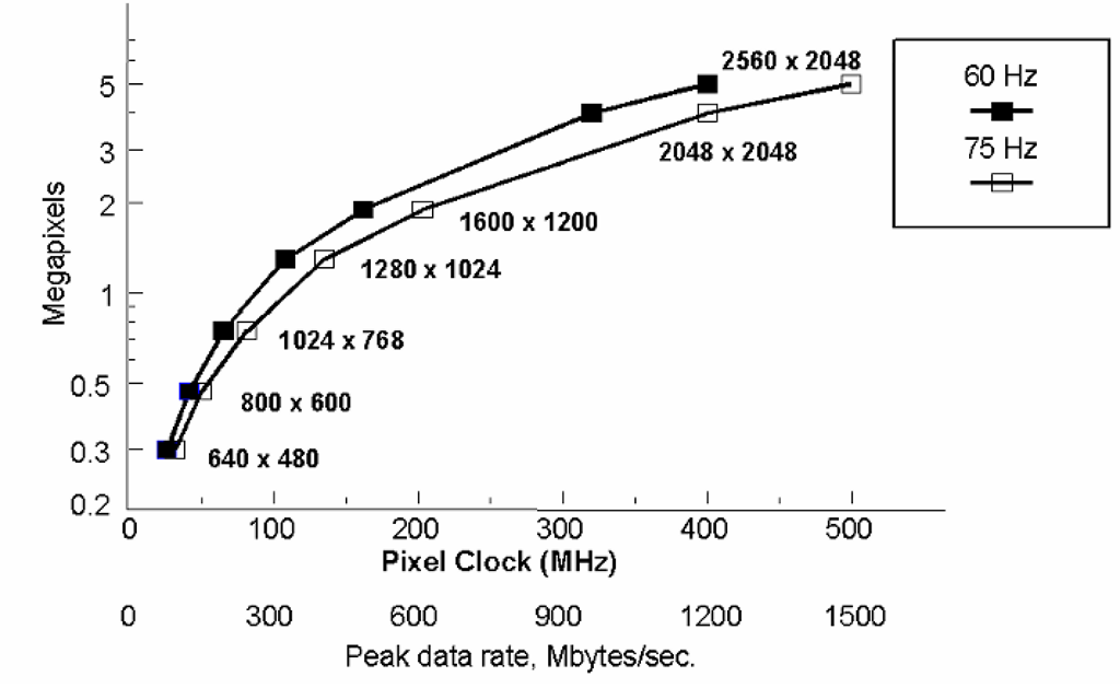
Standard broadcast television, however, is actually near the low end of the information rate scale, when compared to other systems and applications. Computer displays, medical imaging systems, etc., typically use far higher pixel counts and frame rates. Fortunately, at least from the perspective of ease of analysis, these are commonly considered as having discrete, well-defined pixels, with fixed spatial formats. A graph showing the pixel clock rate required for a range of standard image formats, at various frame rates, is shown as Figure 5-1. This chart assumes an overhead of about 25% in all cases, a typical value for systems based on the requirements of CRT displays. Note that the pixel rates shown here range from a low of a few tens of MHz to several hundreds of MHz. In their simplest forms, most of the systems using these formats will employ straightforward RGB color encoding, and generally assume at least 8 bits/color (24 bits/pixel) will be required for realistic images. This results in the peak data rates listed as the second line of labels for the X-axis.
Figure 5-1 Pixel rates for common image formats. These are based on an assumption of 25% overhead (blanking) in each case. If the typical 24 bits/pixel (3 bytes) is assumed, the transmission of such video signals represents peak data rates, in megabytes per second, of simply three times the pixel rate.
We again are reminded that image transmission, especially at the high frame rates required for good motion portrayal and the elimination of “flicker”, is an extremely demanding task. In fact, motion video transmissions are among the most demanding of any information-transmission problem, with the task complicated by the fact that the data must continue to flow in a steady stream to produce an acceptable, convincing representation at the display.
Compression
This tells us why, for instance, video transmission is for the most part not practical with wireless interfaces, unless some sophisticated techniques are used. With the exception of broadcast television, which is a unique combination of some ingenious compromises, “wireless”, over-the-air transmission of imagery has been restricted to either very low resolution, low frame rates, or both. The “PicturePhones” shown at the 1964 World’s Fair may have been intriguing, but they were woefully impractical at the time; the telephone network could not provide the capacity needed to support a nation of video-enabled telephones. Today, such devices are finally appearing on the market – although not yet with the image quality that some may expect, and we are also seeing the advent of high definition broadcast television, or HDTV. Dr. Shannon’s theorem has not been invalidated, however; instead, more efficient means of conveying image information have been developed. These all fall under the general term compression, meaning a reduction in the actual amount of information which must be transmitted in order to convey an acceptable image. Compression methods fall into two general categories – lossless compression techniques, which take advantage of the high level of redundant information present in most transmissions (enabling the removal of information with no impact on the end result), and lossy compression, which in any form literally deletes some of the information content of the transmission, in the expectation that it will not significantly impact the usability of the end result.
A simple example of lossless compression might be given as follows: Suppose I am sending you a video signal which comes from a camera aimed at a blank white wall. This represents a situation in which the signal contains an extreme amount of redundant information; rather than repeatedly sending the same image over and over again, it would be far more efficient to simply send it once, and then to send a command which tells the display to continue to show that same image until I send a different one. This assumes certain capabilities in the receiving display, but it does significantly reduce the load on the transmission channel. However, there is a price to pay for this; if the signal were corrupted during the transmission of that one image, say by a “spike” of noise on the line which affected several lines, that corrupted image will continue to be displayed for a long time. Removing redundant information always increases the vulnerability of the system to noise, since the remaining information now carries greater importance – if it is not received correctly, there is no additional information coming in through which it may be corrected.
Lossy compression, in one of its simplest forms, is seen in standard broadcast television. In the above examples, you may have noted that some of the numbers did not seem to add up; if television gives us the equivalent of 330 lines of resolution per frame, and yet is operating at a 60 Hz rate, the line rate given (15.75 kHz) was too low.
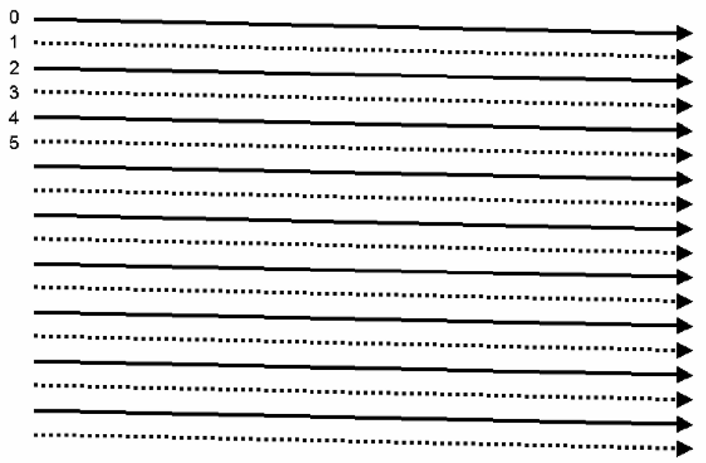
Figure 5-2 Interlaced scanning, a simple form of lossy compression used in analog television. Rather than transmitting all lines of the image in a single frame, the frame is divided into even and odd fields (one containing only the even-numbered scan lines (solid in the diagram above), and the other the odd). These are interleaved as shown above at the receiver, to create the illusion of the full vertical resolution being refreshed at the field rate. (Note that interlaced systems normally will require an odd number of lines per frame, such that one may consider each field as including a “half line.” This accounts for the offset needed to properly interleave the two fields.)
In fact, you may recall the standard number of 525 total lines per US standard television frame, and so we would expect an even higher rate – something in excess of 30 kHz! Such a rate, however, would have required a video bandwidth far in excess of what was allowable, and so a simple form of lossy compression was employed. Instead of sending the full 525 lines of the frame every 1/60 of a second, the standard television system sends the odd lines during the first 1/60 second period, and then the even lines during the next. Exactly half of each frame has been removed, but we still see an acceptable image at the receiver as the viewer’s visual system merges the two resulting “fields” (Figure 5-2). There clearly has been a loss of information, however, and this is where the “330 lines” number comes from. The original 525 line frame actually has around 480 active lines (those containing image content), but this interlaced transmission technique forces a reduction the effective resolution delivered at the final display. “Interlacing” is, fundamentally, a simple form of lossy compression.
Specific details of both the analog broadcast television systems, and the more sophisticated compression techniques employed in digital high-definition television, are covered in later topics. At this point, it should be noted that state-of-the-art compression techniques have been demonstrated which reduce the required data transmission rate by factors of over well over 50:1, while still providing very high quality images at the final display.
Error Correction and Encryption
Not all of the processing performed on signals, especially in modern digital systems, results in a reduction in the amount of data to be transmitted. Two processes which can impose significant additional requirements on the channel capacity are the use of error detection and/or correction techniques, and the use of various types of data encryption. Additional data encoding methods may also be encountered which add to the burden of the interface by increasing the total amount of data to be conveyed.
Robust error detection/correction methods are only rarely employed in the case of image data transmission, especially in a motion-video system. Typically, error rates are sufficiently low such that the errors that do occur are not noticeable in the rapidly changing stream of images. However, critical applications may require images to be known to be error-free to a high-degree. This might occur, for instance, in the case of high-resolution still images in the medical field. Error detection and correction may also be incorporated in some systems employing high levels of compression, due to the increased importance of receiving the remaining data correctly, as noted above. In any event, the techniques employed may in general be viewed as the functional opposite of lossless compression; to protect against errors, some degree of redundancy must be added back into the transmitted information.
Encryption is more commonly seen in video or display interfaces than error correction, at least when dealing with uncompressed data. The term is used here to refer to any technique that modifies or encodes the data for the purpose of security; essentially to render it useless unless you are able to decrypt it (and therefore are presumably an authorized user of the information). In the case of video information, the more common application of data encryption comes in the form of various copy-protection schemes. These are intended to make it impossible (or at least, impractically difficult) to make an unauthorized copy of the material, most often “entertainment” imagery such as movies or television programming. While some forms of copy protection have been used with analog video transmission, this became significantly more important with the advent of digital interfaces and recording. As these technologies potentially allow for “perfect” reproductions in practically unlimited generations, ensuring the security of copyrighted material was a major concern to the developers of digital display interface standards.
Other forms of data encoding may be required to optimize the characteristics of the transmission itself. One example common in current practice is the encoding used in the “Transition Minimized Differential Signalling” (TMDS) interface standard, now the most widely used digital interface for PC monitors.This is done not for error correction or encryption purposes, but rather to both minimize the number of transitions on the serial data stream and to “DC balance” the transmission (such that the transmitted signal spends half the time in the “high” state, and the other half “low.”) Note that this represents a 25% increase in the required bit rate of the transmission over what would be expected from the original data.
Physical Channel Bandwidth
Having looked at the data rates required for typical display interfaces, we must now turn to the characteristics of the available physical channels, both wired and wireless. In the case of wireless, “over-the-air” transmission, we can quickly see that full-motion video is typically going to be restricted to the higher frequency ranges, where there is spectrum available to meet the requirements of such high data rates. Again, broadcast television is an excellent example; even with the relatively low resolution of standard TV, the minimum channel width in use today is the 6 MHz standard channel of the “NTSC” system used in North America; other countries use “channelizations” as wide as 8 MHz. This restricts television transmission to the VHF range and above; in the US, for example, the lowest allocated television channel occupies the 54-60 MHz range. This single channel is roughly six times the width of the entire “AM” or “medium wave” broadcast band; fewer than five such channels would occupy the entire “short wave” spectrum from 1.5 to 30 MHz.
The UHF (above 300 MHz), microwave (above 1 GHz) and even higher frequencies are best suited for wide-bandwidth video transmissions, but these frequencies are problematic in terms of being restricted to line-of-sight transmission, and requiring significantly higher transmitter power, for acceptable terrestrial transmission, than the short wave and VHF bands. Recently, the advent of direct broadcast by satellite (DBS) systems, using compressed digital transmission, has opened a new paradigm for wireless television transmission, using extremely high frequencies but requiring only small, relatively simple receiving systems. Terrestrial broadcasting is also benefiting from digital compression and transmission techniques, which permit multiple standard definition signals, or a single transmission of greatly enhanced definition, to be transmitted in the standard 6-8 MHz terrestrial broadcast channel, and at lower power levels than required for conventional analog television.
The high-resolution, high-frame-rate, progressively scanned images common in computer graphics, medical imaging, and similar applications still require higher data rates than is currently practical for standard wireless transmission systems. Thus, the “display interface” in these fields almost always requires some form of physical medium for the transmission channel. This would almost always be some form of wired connection, or, in the one significant example which spans the gap between “wired” and “wireless,” a connection employing optical fiber.
Wired interconnects, employing twisted-pair, coaxial, or triaxial cabling, are capable of carrying signals well into the gigahertz range, and so (assuming adequate transmitter and receiver devices), are certainly capable of dealing with practically any video transmission which is likely to be encountered. However, such connections are not without their own set of problems. First, due to the high frequencies involved, wired video connections almost always require consideration as a transmission-line system, meaning that the characteristic impedance of the line and the source and load terminations must be carefully matched for optimum results. Impedance mismatches in any such system result not only in the inefficient transfer of signal power, but also distortion of the signal through reflections travelling back and forth along the line.
A wired connection also results in the potential for exposing the signal to outside noise sources, through capacitive or inductive coupling or straight EM interference, and conversely makes it possible for the signal itself to radiate as unwanted (and potentially illegal, per various regulatory limits) electromagnetic interference, or EMI. This adds the requirement that the line and its terminations not only be impedance-controlled, but generally that some form of “shielding” be incorporated. External signals are not the only concern here; in systems using multiple parallel video paths, as in the case of separate RGB analog signals or even parallel digital lines, the signals must be protected from interfering with each other (a problem generally referred to as crosstalk).
Systems employing multiple physical paths, such as the standard RGB analog video interconnect mentioned above, or digital systems with separate paths for various channels of data and their clock, must also present the data to the receiver without excessive misalignment, or skew, in time. This requires that the effective path length of all channels be carefully matched, meaning that not only must the physical lengths be held to close tolerances, but also that the velocity of propagation along each line be similarly matched. Such rigorous requirements on the physical medium – the cable – itself can add considerable cost to the system, and so an important distinction between various interfaces is often the relative skew of the source outputs, and the skew tolerance of the receiver circuit design. More tolerant designs at each end of the line permit more generous tolerances on the cabling, and so lower costs.
All practical physical conductors exhibit non-zero resistance, and no practical insulating material offers infinite resistance. In addition, any practical cable design will also exhibit a characteristic impedance which is not flat across the spectrum, and will present significant capacitive and/or inductive loads on the source. In simpler terms, this means that all cables are lossy to a certain degree, and further that this loss and other effects on the signal will not be independent of frequency. This will limit the length of cable of a given type which may be used in the system, at least in a single length. Quite often, active circuitry – a buffer amplifier in analog systems, or a repeater in digital connections – must be inserted between the source and receiver (display) to achieve acceptable performance over a long distance.
Finally, placing a conductive link between two physically separate products always introduces concerns of a signal quality and regulatory nature, in addition to some non-obvious potential problems from the standpoint of the DC operation of the system. Due to the common requirement for the signal conductors to be shielded, connecting video cables of any type most often means a direct connection between the grounded chassis of the two pieces of equipment Noise potentials, or in fact any potential difference between the two separate products, will result in unwanted currents flowing via this connection (Figure 5-3a). These can, of course, result in noise appearing on the signal reference connection, and so interfere with the signal itself, but also can be radiated by the cable or by the equipment at the opposite end of the cable from the noise source. Ensuring that the high-frequency currents on the connection remain balanced both reduces cable emissions and improves the signal quality; this can be achieved, or at least approached, through the use of true differential signal drivers and receivers, and/or by adding impedance into the path of possible common-mode currents (for example, by placing ferrite toroids around the complete cable bundle, Figure 5-3b).
A DC connection for the signals themselves can also be problematic. Given the relatively low signal voltages typical of display interfaces, even providing a substantial ground connection through the cable will not ensure that the source and receiving devices are at the same DC reference potential. Besides the problem with unwanted currents, as mentioned above, offsets in the reference at either end of the cable can degrade or disable the operation of the driver or receiver circuits. This will very often result in a requirement for AC coupling (either capacitive or inductive) at least at one end of the cable.
Before moving to specific concerns for analog and digital interfaces, we should also briefly consider an alternative mentioned earlier.
Figure 5-3 Return currents and noise in wired signal transmission systems. In any such system, it is desirable that both the “forward” signal current and the return travel along the intended path, as defined by the cable. However, any additional connection (such as the safety grounds) between the source and load devices represents a potential return path, and signal return current will flow along this path in proportion to its impedance vs. the desired return (a). This is both a source of undesirable radiated emissions and a means whereby noise may be induced into the transmitted signal. Increasing the impedance of these unwanted paths may be achieved by adding a ferrite toroid around the conductor pair (b); as both the intended current paths pass through this, it represents no added inductance for these.
Optical connections, using light guided by optical fibers as the transmission medium, solve many of the problems, described above, of electrical, wired interfaces. They are effectively immune to crosstalk and external noise sources, cannot radiate EMI, and can typically span longer distances than a direct-wired connection. Further, since optical-fiber interfaces do not involve an electrical connection between the display unit and its host system, no safety current or noise concerns exist. We might also expect optical connections to provide practically unlimited capacity; the visible spectrum alone spans a range of nearly 400 terahertz (4 x 10¹⁰ Hz), which one would think would be enough to accommodate any data transmission. Unfortunately, it has proven difficult to manufacture electro-optical devices capable of operation at very high data rates. Only recently have practical systems capable of handling gigahertz-rate data become available. The optical cabling itself has also been historically relatively expensive, and difficult to terminate properly. But optical connections are rapidly moving into the mainstream, and promise to become significant in the display market in the near future.
Performance Concerns for Analog Connections
In the case of an analog interface, the job of the physical connection is to convey the signal from source to receiver with a minimum of loss and as little added noise and distortion as possible. (Distortion can, in fact, be considered as a form of noise in the broadest sense of the word – anything that is not a part of the intended information is noise.) In short, we are attempting to maximize the ratio of signal to noise at the receiver. Given the range of frequencies used in video, and the typical lengths of the physical interconnect, this first of all requires that the impedance of the transmission path be maintained at a constant value throughout the path. Impedance discontinuities result in reflections of part of the signal power, which means both a loss of power and potentially a distortion of the signal. At the same time, the signal must be protected from external noise sources (including other signals which may be carried by adjacent conductors), which generally means some form of shielding and/or filtering. Finally, the materials used and the design of the cabling and connectors must be chosen such that signal losses be kept to a minimum, consistent with the other requirements.
Cable impedance
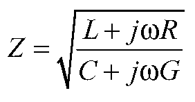
Any physical conductor (or more properly, conductor pair, since there must always be some return path) may be modelled as a series of elements as shown in Figure 5-4. In this model, the L and C elements represent the distributed inductance and capacitance of the cable, respectively, while the R and G elements are distributed losses. These losses are the result of the resistance of the conductor itself (modelled as the distributed R), and the fact that the insulating material between conductors can never have infinite resistance (modelled in this case as a distributed conductance, G). If we assume an infinite length of the cable being modelled – which is then an infinite number of such sections – the impedance seen looking “into” the cable at the source end is given by
Figure 5-4 Distributed-parameter model of a conductor pair. Any cable may be modelled as an infinite series of distributed elements as shown above; these represent the distributed series inductance and resistance of the conductors (the series elements Ld and Rd), plus the capacitance and conductive losses between the conductors (Cd and Gd). These are considered as being distributed uniformly along the length of the cable. The values of each is given in terms of their value per unit distance; for example, the distributed capacitance is typically given in terms of picofarads per meter (pF/m).
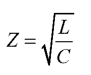
This is referred to as the characteristic impedance of the cable, or as it would more commonly be referred to at frequencies where this is of concern, the transmission line. Per this model, this impedance varies with frequency. However, note that the frequency dependence in this case is associated with the resistive and conductive loss factors; if it can be assumed that the product of these factors and the frequency in question are small compared to the distributed L and C elements, this equation reduces to
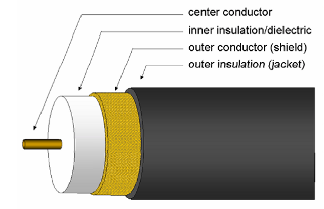
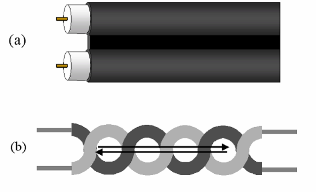
Under these circumstances, then, the characteristic impedance of the cable is independent of frequency, and depends solely on the distributed inductance and capacitance of the cable. These are determined by the size and configuration of the conductors, plus the characteristics of the insulating or dielectric material between them. In general, the conductors may be configured so as to minimize the distributed inductance or capacitance, but not both simultaneously. Minimizing the distributed inductance generally means minimizing the “loop area” defined by the conductors in question, which implies placing the conductors in close proximity and ideally causing the currents in both directions to follow the same average path in space. Coaxial construction (Figure 5-5), in which one conductor is completely surrounded by the other, is an example of a configuration which does this. However, minimizing the distributed capacitance is a matter of keeping as little of the conductors are possible in close proximity; the farther the conductors are separated, or the lower the area placed in proximity, the lower the capacitance. The best that can usually be done in this direction, in terms of a practical conductor configuration, is the case of parallel conductors held a fixed distance apart by an insulating support, the “twinlead” type of cable (Figure 5-6a). As this construction results in much greater “loop area” than a coaxial design, the capacitance reduction comes at the expense of greater inductance. In the coaxial cable, exactly the opposite happens – the distributed inductance is minimized at a cost of greater capacitance. As a result,coaxial cable types tend to have lower characteristic impedances (most commonly in the 50-100 Ω range) as compared with twinlead types (commonly 100-300 Ω, and in some cases as high as 600-800 Ω). The most common standard characteristic impedance for analog video interconnects is 75 Ω, so these are almost always constructed of coaxial cable.
Figure 5-5 Coaxial cable construction. This form is ideal for ensuring that the forward and return currents follow the same average path in space, but at a cost of increased capacitance and losses, and therefore a lower characteristic impedance, than other cable designs.
Figure 5-6 Twinlead and twisted-pair construction. In the twinlead type (a), the conductors are held parallel and at a fixed separation distance by the outside jacket; the portion between the conductors is often made as thin as practical, to minimize losses and inter-conductor capacitance. This form of construction provides significantly lower losses and capacitance than the coaxial design, and so a higher characteristic impedance, but does not provide coaxial cable’s “self-shielding” property. Twisting a pair of conductors together (b) holds the two in close physical proximity, and causes the forward and return currents to follow the same average path. This minimizes both the possibility of induced noise on the lines, and the degree of unwanted radiation from the cable.
A straight “twinlead” cable design (Figure 5-6a), while fairly common in some applications (such as low-loss antenna cabling for television), is not commonly used for video signal cabling, as it suffers from being very vulnerable to external noise sources. Both capacitively and inductively coupled noise can be reduced significantly, however, by simply twisting the pair of conductors as shown in Figure 5-6b. Such a twisted-pair cable provides approximately the same characteristic impedance as the twinlead type, other factors being equal, but noise is reduced as external sources will couple to the cable in the opposite sense each “loop” in the pair, resulting ideally in cancellation of the noise. Twisted-pair construction is very common in communications and computer interfaces, such as telephone wiring and many computer-networking standards. Some very inexpensive analog video cables have been produced and sold using shielded twisted-pair construction, but these are adequate only for very low-frequency applications and very short distances. They are to be avoided for any serious analog video use.

