1. Crankshaft Oil-hole Drillings
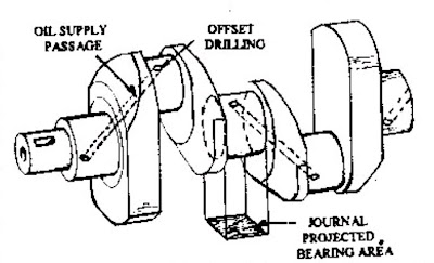
Oil from the main oil gallery reaches each individual main-journal and bearing. Oil is fed through a central circumferential groove in the bearing and it completely surrounds the central region of the journal surface. Diagonal oil hole drills are provided in the crankshaft which pass through the webs between the main and big-end journals (Figs. 3.62 and 3.65) for lubrication of the big-end journal. For effective lubrication of the big-end, these oil holes emerge from the crankpin at about 30 degrees on the leading side of the crank’s TDC position. The drilled oil passages should not be close to the side walls of the webs or near the fillet junction between the journal and the webs to avoid high stress concentration, which may cause fatigue failure. Also the oil holes on the journal surfaces must be chamfered to reduce stress concentration, but excessive chamfering can destroy the oil film.Crankshaft with single diagonal oil drillings.
2. Lubrication Systems for Petrol Engines
In order to ensure adequate supplies of oil to the engine parts, a reservoir of oil is provided by the sump which is the lower part of the lubrication system and in automobile engines the sump is the oil pan. From the reservoir, oil is distributed throughout the engine either by the splash system or the full pressure system. In case of two-stroke engines, the crankcase cannot be used as an oil reservoir. The lubrication, in this case, is provided by mixing a small proportion of oil with petrol.
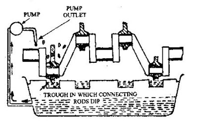
In the splash system the oil is maintained in little troughs (Fig. 11.9). There are dippers at the ends of the connecting rods to splash the oil on the various parts like cylinder walls, camshafts, gudgeon pins etc. as they travel through the oil troughs towards the bottom of the stroke of the piston. The oil is supplied to the main bearings under pressure due to an oil pump through drilled passages, in the crankcase, called galleries. The oil pump also replenishes the troughs. The system is now practically obsolete.
Splash lubrication system.
3. Full Pressure System
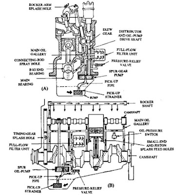
Automobile engines today use ‘forced-feed’ lubrication systems, generally of the wet-sump type in which the sump acts as both an oil-drain return and a storage container. A rotary-type oil-pump provides forced feed. The pump may be driven directly from the crankshaft or indirectly from the camshaft or any auxiliary shaft (Fig. 11.10). Oil from the sump reaches the pump through the submerged gauze strainer and pick-up pipe. The oil is then compressed, which passes through a drilling to the lubrication system.
A pressure-relief valve positioned on the output side of the pump controls the oil pressure. If the oil pressure becomes too high, the relief valve opens and bleeds surplus oil back to the sump. The relief valve may be installed on the filter unit, the crankcase, or the pump housing.
The oil-pump forces the oil through drillings in the crankcase to a cylindrical full-flow filter unit. The oil circulates around the filter bowl, passes through the filter towards its centre, and flows out to the main oil passage, called main oil gallery (Figs. 11.10 and 11.11) which lies parallel to the crankshaft. In most car and commercial vehicle engines, the oil gallery is formed by drilling a hole in the crankcase for full length of the engine and plugging the ends.
Main- and Big-end Bearing Lubrication.
The oil is fed to the crankshaft main journal bearings and in some cases to the camshaft bearings (Figs. 11.10 and 11.11) through various branch cross-drillings in the crankcase. A few heavy commercial engines use a separate pipe located underneath the main-bearing caps and by pedestal brackets. Drillings in these brackets connect the gallery-pipe oil to the main bearings. By diagonal drillings in the crankshaft a continuous oil is fed to the big-end bearings from the oil grooves around the main-bearings liners. These drillings pass from the main-bearing journal to the big-end crankpins (Fig. 11.10) through the crankshaft web.
Forced-feed lubrication system.
A. Front sectional view. B. Side sectional view.
Crankshaft Oil Passages.
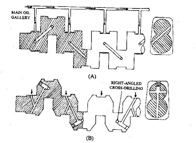
Crankshaft oil passages feed oil from the main-journal bearing to the big-end journal. In its simplest form, the oil passage is a diagonal drilling (Fig. 11.27A) running from the main journal to the big-end journal. Normally the diagonal hole is drilled at an angle to the crank-web centre-line so that, when the crank-pin is in the TDC position and combustion force pushes the connecting rods downwards, some oil still enters between the journal and the bearing. It is because if the exit of the diagonal hole is exactly at the top of the big-end journal, oil can not enter between the bearing and the journal in the TDC position. Additionally the effective projected bearing area is also reduced by chamfered oil hole.
To have an improvement in oil delivery, a cross-drilling (Fig. 11.27B) runs straight through the big-end journal and a diagonal drilling from the main-bearing journal intersects the big-end cross-drilling. Another hole is also drilled diametrically opposite the diagonal-hole’s entry in the main journal, so that when the bearing is loaded at the top or the bottom of the stroke, the other side of the bearing permits oil to enter.
Crankshaft oil passages.
A. Crankshaft with single oil passage
B. Crankshaft with diagonal web passage and right-angled cross-drilling in the big-end journal.


