Abstract. In this paper, we propose an adaptive patch-based inpainting algorithm for image block error recovery in block-based coding image transmission. The recovery approach is based on prior information – patch similarity within the image. In order to keep local continuity, we recover the lost pixels by copying pixel values from the source based on a similarity criterion according to the prior information. The pixel recovery is performed in a sequential fashion, such that in this manner, the recovered pixels can be used in the recovery process afterwards. In order to alleviate the error propagation with sequential recovery, we introduce an adaptive combination strategy which merges different directional recovered pixels according to the confidence of the estimated recovery performance. Experimental results show that the proposed method provides significant gains in both subjective and objective measurements for image block recovery.
Keywords: Image error recovery, Inpainting, Error propagation, Combination strategy.
Introduction
With the development of multimedia communication, image/video transmission is becoming more and more important. Unfortunately, transmission error is inevitable on most channels such as wireless channels and the Internet which are not reliable enough to guarantee error-free transmission. Meanwhile, existing multimedia compression standards such as JPEG, MPEG-2 and H.264 [1] use the variable length coding (VLC) with block-based structure. The bit stream encoded by those standards is very sensitive to transmission errors [2]. Even one single bit error may cause the loss of a whole block. And in video transmission, the mistakes in current blocks even propagate to the following blocks or the following frames, which will result in serious degradation in the visual quality of the decoded image.
Error recovery as a post-processing module is widely adopted to alleviate the negative effect of the erroneous blocks [3] which attempts to reconstruct corrupted pixels utilizing the available neighbor information, without modifying source and channel coding schemes. Comparing to other existing error resilient approaches [4] as the Forward Error Correction and the interactive methods, no extra delay or redundant information will be added to the bit stream.
In general, according to correlation information, error recovery methods could be divided into two classifications [5]: spatial error recovery (SER) and temporal error recovery (TER). The former utilizes spatial neighbor information to fill the missing area whereas the latter utilizes temporal information from successive frames. The spatial error recovery is often adopted in image sequence, intra coded frame and areas of low temporal redundancy in inter-coded frame.
A number of spatial recovery approaches have been proposed already in the literature. Bilinear interpolation [6] is a simple and efficient method which utilizes the nearest correctly decoded pixels to reconstruct the lost areas with weighted averages of these pixels. Rane et al. [7] estimate the lost information in the frequency domain based on the spatial smoothing constraint on the reconstructed blocks. While the obtained results are fairly good, these algorithms provide smooth reconstructions in image regions. Several methods try to mitigate this problem by interpolating missing pixels along estimated edge directions such as directional interpolation [8] and verge points based method [9]. In [10], error recovery is performed recursively for bands of missing pixels, using border pixels of surrounding blocks and already concealed pixels of the recovered block. The concept of sequential error recovery is also followed in the orientation adaptive sequential interpolation (OASI) approach [11].
Some methods address the problem of recovering missing data from different point of view. The best neighborhood matching (BNM) method [12] exploits block wise similarities within an image to replace whole missing blocks through a search process in the vicinity. Texture inpainting method, triggered in part by texture synthesis [13], has shown promising results on restoring corrupted image data, which is based on the similarity between their local neighborhood and the surrounding neighborhoods. Criminisi et al. [14] present an order-based image inpainting method that extends the texture synthesis approach by imposing higher priorities in the restoration order for pixels lying in the neighborhood of edges, thereby preserving better edge sharpness and continuity. Zhang et al. [15] introduce a recovery method utilizing multidirectional inpainting. In [16], the authors propose a non-local variational model to address the texture-oriented inpainting problem and provide impressive results. Bertalmio et al. [17] decompose the image into two functions, one for the texture ingredient and the other for the geometry structure of the image. Then they fill in the texture component using texture synthesis, and fill in the structure part using a classical inpainting approach based on partial differential equation models [18, 19].
This paper intriduces an adaptive patch-based inpainting algorithm for image block recovery in block-based coding image transmission. The proposed approach is based on prior information – patch similarity within the image. By taking advantage of this information, we recover the lost pixels by copying pixel values from the source based on a similarity criterion to keep local continuity. The pixel recovery is performed in a sequential fashion in which the recovered pixels, as well as the uncorrupted pixels in the neighbor area, can be used in the recovery process afterwards. In order to alleviate the error propagation with sequential recovery, we proposed an adaptive combination strategy to reconstruct the lost block, which merges different directional recovered pixels according to their confidence. The confidence is estimated by the dissimilarity and the amount of reliable information in the patch.
The remainder of this paper is structured as follows. In section 2, we give an overview of the proposed adaptive patch-based inpainting algorithm. Section 3 presents the proposed method in detail. Section 4 gives the results and comparisons, and conclusions are drawn in section 5.
The Framework
Before the application of our image recovery approach, it is assumed that that we can locate the error region in the decoded video or image with some error detection algorithms.
Most of traditional error recovery methods, such as bilinear interpolation, directional interpolation and OASI, perform as a low pass filter or directionally low pass filter in nature. They cannot recover accurately the sharp edge and texture within the lost region, however, the edge and texture information is very important for the human vision system. It is introduced by the following two reasons [12]. First, the information source to estimate pixels in the missing blocks is the neighboring pixels in a very limited local region. Second, these methods rely on some predefined constraints on the lost blocks such as the recovered blocks should be smoothly connected with adjacent regions either in spatial or in transform domain.
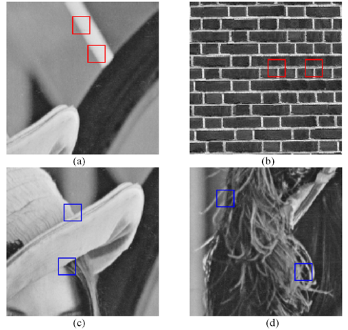
In order to overcome the above problems, the BNM method exploits block wise similarities within an image to replace whole missing blocks through a search process in not only neighboring regions, but also remote regions within the image. The method can reconstruct the simple texture block (Fig. 1a) and single strong edge (Fig.1b) effectively, and it can keep the sharp edge and details of texture in the lost block. However, BNM fails to recover the region with multiple edges (Fig.1c) or complex texture (Fig.1d), because there are much less matching possibilities for the lost blocks in the image. The BNM method takes the missing block as a whole to find a similar area in the vicinity. When the missing block is large, such as 8×8 or 16×16 which is very common in block-based image-coding systems, it is very difficult to find the similar area especially for the situation in Fig1.c and d. Based on this observation, we adopt the approach of patch-based inpainting to reconstruct the missing regions. The approach grows the missing area pixel by pixel, based on prior information – patch-wise self-similarity within the image. By taking advantage of the information, we recover the lost pixels by copying pixel values from the source based on a similarity criterion to keep local continuity. The pixel recovery is performed in a sequential fashion in which the recovered pixels, as well as the uncorrupted pixels in the neighbor area, can be used in the recovery process afterwards [11]. This sequential fashion introduces a bias on the later recovered pixels. Because the later recovered pixels depend on the previous recovered pixels, error propagation is inevitable. The quality of the recovered image is highly influenced by the order in which the filling process proceeds. The pattern of error propagation varies with the recovery order. In order to alleviate the error propagation with sequential recovery, we perform the patch-based inpainting algorithm from different directions. Then we calculate the confidence of the interpolated pixels from different directions, and finally combine them by adaptive weighting according to the confidence.
Fig. 1. Textural and edge images
The proposed adaptive combination strategy is inspired by the work in [11]. The authors adopt a linear merge strategy, in which the weights only depend on the distances of the given pixel to the four borders of the block. These distances cannot fully reflect the contribution of the pixels from different directions to the interpolated pixel. In our method, we introduced two confidence measurements to evaluate the contribution: reliability confidence and similarity confidence. The former measures the amount of the reliability of the available pixels for recovering the missing one. The latter evaluates the quality of the contribution of the available pixels to the interpolated pixel. And the final weights are determined by the two confidence measurements together.
Based on the above analysis, the reconstruction of lost blocks follows three main steps:
a) Choose the scan direction as recovery order;
b) Patch-based inpainting for each determined direction;
c) Merge them by adaptive weighting according to the confidence.
The Framework
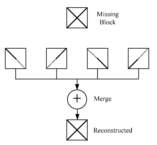
In the proposed adaptive patch-based inpainting algorithm, we first determine the recovery order for single-directional pixel interpolation. For each determined recovery order, we then recover the missing block using patch-based inpainting algorithm based on patch-wise similarity within the image. Finally, we reconstruct the missing block by an adaptive combination strategy according the confidence of the intermediate recovered pixels. A sketch map of the procedure of our method is shown in Fig.2.
Fig. 2. Reconstruction of lost blocks
Recovery Order
For single directional error recovery, error propagation is inevitable because the later recovered pixels depend on the previous recovered pixels. Different recovery orders may introduce different error propagation patterns. In practice, a specific recovery order is very effective for its specific area and direction of edge in the image. For example, the raster scanning order from left to right can reconstruct the horizontal edge more accurately than the vertical edge. Moreover, the pixels in the top-left area can be recovered more accurately that those in the bottom-right area. Single order recovery cannot represent the correct and acceptable result especially for the area with complex structure. Each recovery order has its own advantage on its specific area and direction of edge in the image. Therefore, it is expected that we can reconstruct the image with high quality after carefully merging the result from different recovery order, as shown in Fig.2. Theoretically, if there are K continuous corrupted pixels, there are K! different orders to get K! recovery results[11]. The computation is tremendous complex for searching all the orders. In fact, lots of recovery orders are not practical. For example the recovery beginning from the center of the corrupted areas has little available information. It is reasonable to choose several typical orders. In this way, the reconstructed quality doesn’t decrease so much whereas the computation complexity decreases significantly. In our method, we use raster recovery order due to its simplicity of implementation. Starting from each corner, there are two directions to reach the diagonal corner and traversal all the missing pixels. Therefore, we adopt eight single-directional recovery orders, which is introduced by X. Li et al. the detailed information can be found in [11]. Take the top-right corner as an example as shown in Fig.3, the recovery process starts from the pixels in the top-right corner, there are two directions to reach the diagonal corner. In Fig.3a, it recovers the missing pixels with the direction from right to left for each line and repeats the process till the bottom-left corner. The missing block will be recovered using patch-based inpainting in each determined direction.
Fig. 3. Single-directional recovery order from the top-right corner
Patch-Based Inpainting
For each determined recovery order, the patch-based inpainting algorithm uses patch-wise similarity within the image to reconstruct the missing block.
The missing block is referred to as the unknown area, denoted by Ω. The area will now be filled, pixel by pixel, in a raster fashion. The known area, denoted by Φ, provides samples used in the filling process. Let ψ denote the patch. The patch may be a square, rectangle, triangle, or any other shape, and all the pixels within the patch are contiguously connected. In this paper, the patch centered at the pixel po=(i, j) is here defined to be a diamond shaped window, as:
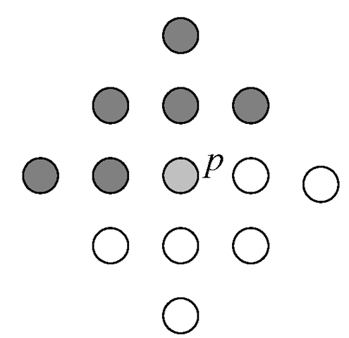
where To is the order of the patch, which controls the size of the patch. A target patch with To =2 is shown in Fig.4, where the light-gray pixel p is the current pixel to be recovered, and the dark-gray pixels represent the available pixels, available means uncorrupted or recovered, the white pixels are the missing pixels. A source patch is the corresponding area in Φ, which has the same shape and size as the target patch.
Fig. 4. Target patch with the order of 2
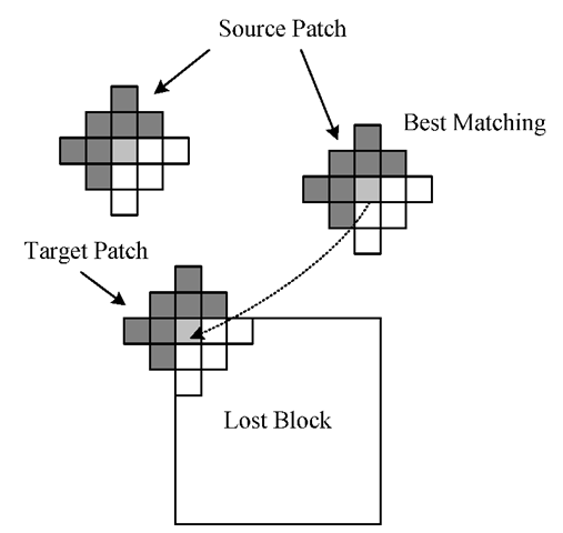
Fig. 5. Pixel recovery
To recover the lost pixels, a search procedure is applied within a large range in the image. The purpose of the search procedure is to find a source patch in the image that has the best similarity with the target patch. We then replace the current pixel being filled in the lost block by the value of the corresponding pixel of the best matched source patch, as shown in Fig.5. Then we recover the rest of pixels using the same approach under the mentioned recovery order.
The similarity of the source patch and the target patch is measured by the normalized sum of absolute differences. Since it is desirable to give more importance to the pixels that are uncorrupted than those recovered previously, different weights are taken for the two kinds of pixels. The pixels within the patch that have not been recovered yet are not taken into account in the distance. The distance between the source patch and target patch can thus be expressed as:
where ps and pt are the centers of the source patch ¥(ps) and the target patch !Pipt), respectively, f(p) is the value of the pixel p, !P(q0) is the diamond window defined in (1) and q0=(0,0), The weight map a(p) is assigned for each pixel in target patch, as follows:
The recovered pixel has some distortion and is given a lower weight compared with the uncorrupted one. And a(p) is set to 0.5 for the recovered pixel, experimentally.
In summary, the patch based inpainting algorithm for single directional recovery proceeds as follows:
1. Choose a pixel to be recovered in Ω as current pixel according to the predetermined recovery order, such as that in Fig.3a.
2. Get the target patch ¥(pt) centered by the current pixel, and search as the best matching source patch ¥(ps) with Ψ(ρt), which minimizes d(W(ps),W(pt)). In this paper, the search range is selected as 32×32.
3. Copy the pixel in the center of the source patch to the current pixel. Alternatively, in order to accelerate the computation, we can fill all the unknown pixels in the target patch by the corresponding pixels in the source patch. In this case, the computation will be decreased significantly with acceptable reduction of the performance.
4. Repeat steps 1, 2, and 3 until all the lost pixels are filled.


