Elimination of Artifacts Due to Occlusion and Discretization
Although processing in image space allows an increase in speed, the images may have artifacts introduced. This can occur in two ways, which we refer to as occlusion and discretization [7] [8]. The occlusion problem arises because there is scene geometry that is missing. This results from the finite aperture of the lens, which allows more of the scene to be visible than would be seen through an infinitesimal pinhole. Thus, without additional input, the colors from parts of the scene that are behind objects would have to be approximately reconstructed using the border colors of visible objects.
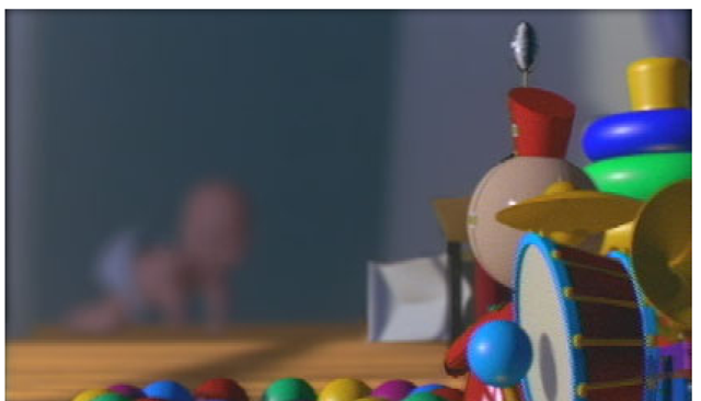
The discretization problem occurs from separating the image by depth. At adjacent pixels in different sub-images, the calculation of depth of field is complicated. This arises because these adjacent pixels may or may not correspond to the same object. An artifacts can be introduced into the image when a single object straddles two subimages and the sub-images are blurred. The artifact arises when the far pixel is averaged with neighboring colors behind the near pixel that do not match the far pixel’s color. The neighboring colors are often black, which is the default background color. Consequently, a black blurred band occurs at the intersection of the object with the separation of the sub-images that it spans, as can be seen in Figure 10.
Object Identification as a Solution for Image Space Artifacts
To eliminate these band artifacts that arise when an object is separated into multiple discrete sub-images, the algorithm attempts to identify entire objects within the image. This eliminates the artifact by avoiding the separation of objects across sub-images. Instead, when a large object straddles several sub-images, each sub-image will include the entire object instead of only a part of that object. Consequently, the object will have minimal artifacts due to blurring.
We will now consider two approaches for object identification to properly blur the scene; these techniques are described in more detail by Barsky et al. [7] [8]. Our first approach uses the depth difference of adjacent pixels to identify objects. In our second approach, the Canny Edge Detection [55] algorithm is applied to draw borders between objects and hence identify them.
Edge Detection Technique for Object Identification
Our first method for identifying objects begins by using a variant of the Canny Edge Detection algorithm [55]. The Canny algorithm takes as input an intensity map for the image, and it convolves the intensity map with the first derivative of a Gaussian function.
Fig. 10. Black bands appear at the locations where the sub-images are separated
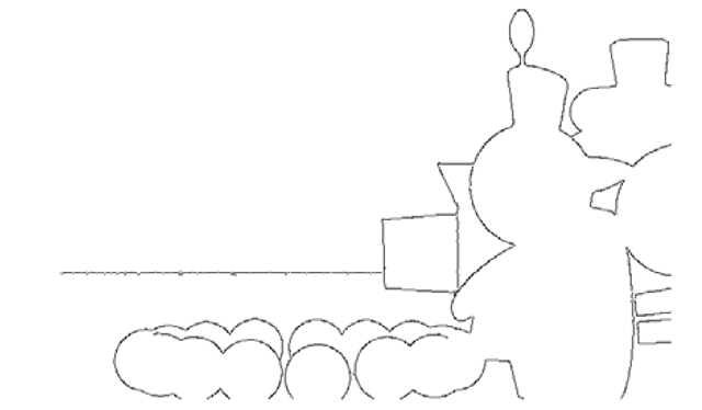
Fig. 11. Using depth map information as input, the edge detection algorithm identifies where object edges lie in the image
The algorithm then marks pixels in the resulting array whose magnitude exceeds a specified upper threshold. These marked pixels are grouped into edge curves based on the assumption that neighboring marked pixels that have consistent orientations belong to the same edge.
Our technique uses a depth map as the intensity map as input to this Edge Detection algorithm. Figure 11 shows the result of edge detection on the example depth map. Using this variant of the Canny algorithm to segment a scene into distinct objects avoids inadequacies that are common to traditional edge detection methods. In particular, using depth information avoids erroneous detection of edges that correspond to the surface markings and shadows of objects in the scene.
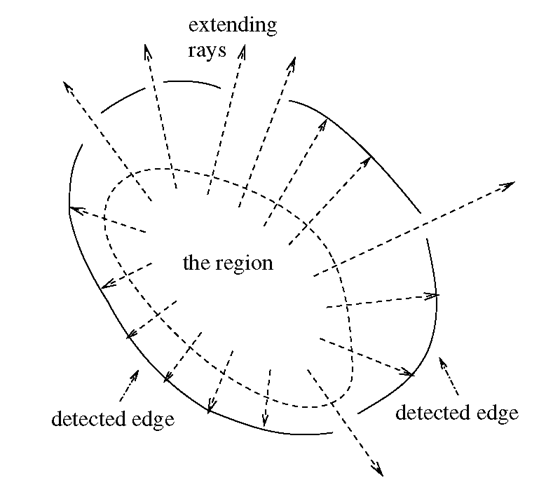
Starting with the region formed by the boundary pixels in the current sub-image, the algorithm extends that region until it is bounded by previously detected edges. Specifically, extending the region involves taking the union of the line segments that begin within the original region and do not intersect the detected edge segments; this is illustrated in Figure 12.
The result of the Canny Edge Detection method to eliminate these artifacts is demonstrated in Figures 13 and 14, focused on the Tin Toy in the foreground, and on the baby in the background, respectively.
Fig. 12. Extending the region involves taking the union of the line segments that begin within the original region and do not intersect the detected edges
Fig. 13. Artifacts eliminated by the Edge Detection technique for image focused on the Tin Toy in the foreground
Adjacent Pixel Difference Technique for Object Identification
The second technique for including points from objects that span several sub-images assumes a surface with a given order of continuity. As input to the algorithm, we select the order of continuity, denoted Cn, of the surface. In addition, the bound on the nth derivative of depth with respect to the image plane coordinates is selected such that adjacent pixels within the bound correspond to the same object. Since image space is a discrete representation of continuous geometry, we use the difference as the discretized counterpart of the derivative. Figure 15 illustrates a first degree difference map for an arbitrary image.
The algorithm assigns an object identifier to each pixel and then groups together those pixels that share an object identifier. Once all objects are located, it is straightforward to determine whether the neighboring colors should be obtained from objects in front of, at, or behind, the current sub-image.
In Section 7.1, Figures 13 and 14 demonstrated the results of the Canny Edge Detection technique. This eliminated the artifacts illustrated in Figure 10 and generated a correctly blurred image. We will now use the Adjacent Pixel Difference technique to generate a similar artifact-free blurred image, which are shown in Figures 16 and 17, focused on the Tin Toy in the foreground, and on the baby in the background, respectively.
Fig. 14. Artifacts eliminated by the Edge Detection technique for image focused on the baby in the background
Fig. 15. An example of a first degree difference map (right) resulting from applying a horizontal difference to the first 16 digits of π (left)


