Greiner-Hormann Polygon Clipping
The last polygon-clipping algorithm we consider is the Greiner-Hormann algorithm ([GreH98]). It is very much like Weiler’s algorithm but simpler. Like the Weiler and Vatti algorithm it handles any sort of polygons including self-intersecting ones. Furthermore, it, like Vatti’s algorithm, can be modified to return the difference and union of polygons, not just their intersections.
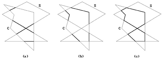
Suppose that we want to clip the subject polygon S against the clip polygon C. What we shall do is find the part of the boundary of S in C, the part of the boundary of C in S, and then combine these two parts. See Figure 3.21. Since we allow self-intersecting polygons, one needs to be clear about when a point is considered to be inside a polygon. Greiner-Hormann use the winding number ω(ρ,γ) of a point p with respect to a parameterized curve γ. They define a point p to be in a polygon P if the winding number of the point with respect to the boundary curve of P is odd. (The oddness or evenness of the winding number with respect to a curve is independent of how the curve is parameterized.)
Polygons are represented by doubly-linked lists of vertices. The algorithm proceeds in three phases. One will find it helpful to compare the steps with those of the Weiler algorithm as one reads.
Phase 1. We compare each edge of the subject polygon with each edge of the clip polygon, looking for intersections. If we find one, we insert it in the appropriate place in both polygons’ vertex lists. If there are no intersections, then either one polygon is contained in the other or they are disjoint. These cases are checked for easily and we then exit the algorithm in this case with our answer.
Figure 3.21. Greiner-Hormann polygon clipping.
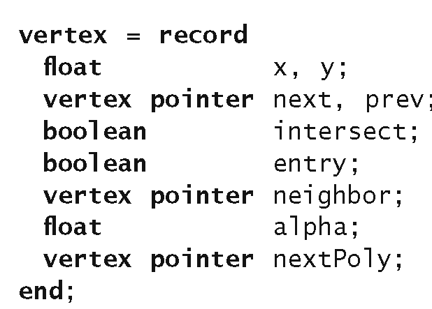
Data 3.3.6.1. The Greiner-Hormann vertex structure.
Phase 2. We traverse each polygon’s new vertex lists marking any intersection points as either entry or exit points. This is done by checking whether the first vertex of each polygon lies inside the other polygon or not using the winding number. The rest of the tagging as entry or exit points is then easy.
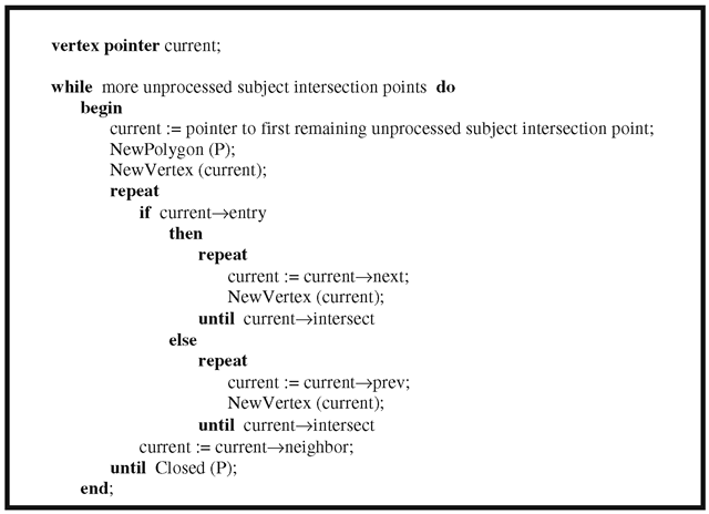
Phase 3. This stage actually creates the intersection polygons. We start at an intersection point of the subject polygon and then move along its point list either forward or backward depending on its entry-exit flag. If we are at an entry point, then we move forward, otherwise, backward. When we get to another intersection point, we move over to the other polygon’s list.
The data structure used for vertices is shown in Data 3.3.6.1. In the case of an intersection point, if the entry field is false, then the point is an exit point. At an intersection vertex in one of the polygon’s vertex lists the field neighbor points to the corresponding vertex in the other polygon’s vertex list. The field alpha for an intersection point specifies the position of the intersection relative to the two endpoints of the edge containing this intersection point. Because the intersection polygon may consist of several polygons, these polygons are linked with this field. The first vertex of each intersection polygon list has its nextPoly field point to the first vertex of the next intersection polygon.
Algorithm 3.3.6.1. Algorithm for Greiner-Hormann’s Phase 3.
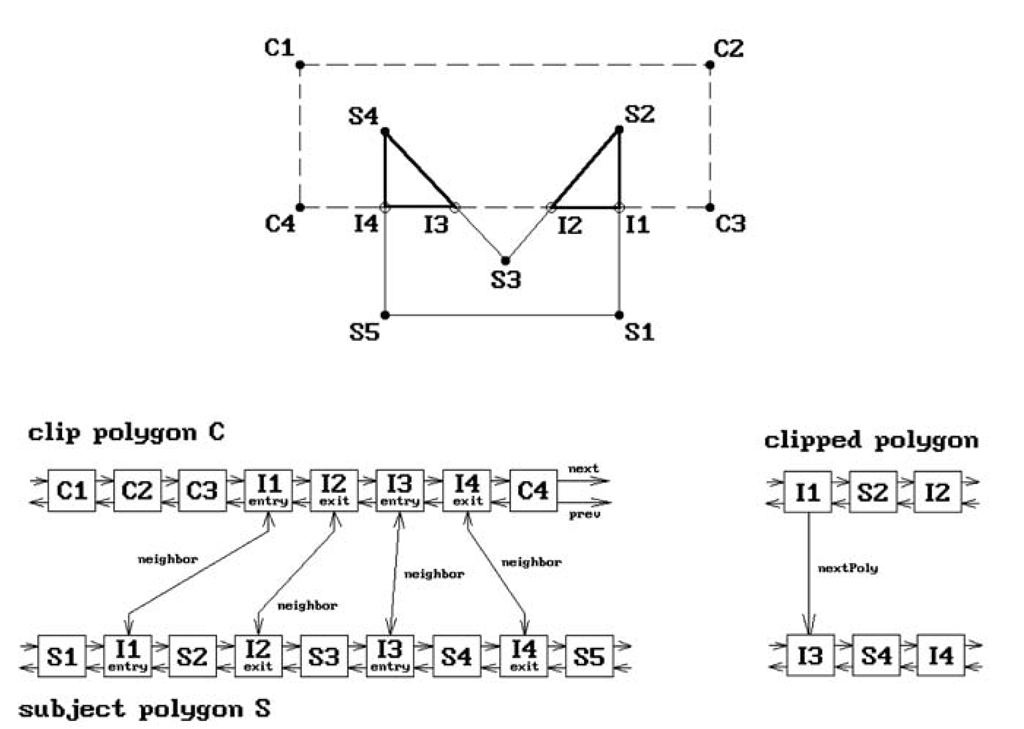
The basic steps for Phase 3 are shown in Algorithm 3.3.6.1. The procedure NewPolygon starts a new polygon P and NewVertex creates a new vertex for this polygon and adds it to the end of its vertex list. Figure 3.22 shows the data structure that is created for a simple example.
The algorithm uses an efficient edge intersection algorithm and handles degenerate cases of intersections by perturbing vertices slightly.
The advantage of the Greiner-Horman algorithm is that it is relatively simple and the authors claim their algorithm can be more than twice as fast as the Vatti algorithm. The reason for this is that Vatti’s algorithm also checks for self-intersections which is not done here. Of course, if one knows that a polygon does not have selfintersections, then the extra work could be avoided in Vatti’s algorithm also. The disadvantage of the algorithm is that one does not get any trapezoids but simply the boundary curve of the intersection. In conclusion, the Greiner-Horman algorithm is a good one if all one wants is boundaries of polygons because it is simple and yet fast.
Figure 3.22. The Greiner-Hormann data structures.
Text Clipping
The topic of text generation and display is a very complex one. We shall barely scratch the surface here.
Characters can be displayed in many different styles and sizes and each such overall design style is called a typeface or font. Fonts are defined in one of several ways:
Bit-Mapped Fonts. Each character is represented by a rectangular bitmap. All the characters for a particular font are stored in a special part of the graphics memory and then mapped to the frame buffer when needed.
Vector Fonts. Each character is represented by a collection of line segments.
Outline Fonts. Each character’s outline is represented by a collection of straight line segments or spline curves. This is more general than vector fonts. An attractive feature of both vector and outline fonts is that they are device independent and are easily scaled, rotated, and transformed in other ways. In either case, one has the option of scan converting them into the frame buffer on the fly or precomputing them and storing the bitmaps in memory. Defining and scan converting outline fonts gets very complicated if one wants the result to look nice and belongs to what is called digital typography.
Two overall strategies that are used to clip text are:
Figure 3.23. A Cyrus-Beck clipping example.
All-or-Nothing String Clipping. Here one computes the size of the rectangle that contains the string and only maps the string to the frame buffer if the rectangle fits entirely into the window in which the string is to be displayed.
All-or-Nothing Character Clipping. Here one clips on a character-by-character basis. One computes the size of the rectangle that contains a given character and only maps the character to the frame buffer if the rectangle fits entirely into the window in which it is to be displayed.
The all-or-nothing approaches are easy to implement because it is easy to check if one rectangle is inside another. The all-or-nothing character clipping approach is often quite satisfactory. A more precise way to clip is to clip on the bit level. What this means in the bit-mapped font case is that one clips the rectangular bitmap of each character against the window rectangle and displays that part which is inside. In the vector or outline font case, one would clip the curve that defines a character against the window using one of the line-clipping algorithms and then scan converts only the part of the character that lies in the window.


