Introduction
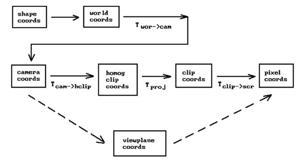
In this topic we combine properties of motions, homogeneous coordinates, projective transformations, and clipping to describe the mathematics behind the three-dimensional computer graphics transformation pipeline. With this knowledge one will then know all there is to know about how to display three-dimensional points on a screen and subsequent topics will not have to worry about this issue and can concentrate on geometry and rendering issues. Figure 4.1 shows the main coordinate systems that one needs to deal with in graphics and how they fit into the pipeline. The solid line path includes clipping, the dashed line path does not.
Because the concept of a coordinate system is central to this topic, it is worth making sure that there is no confusion here. The term “coordinate system" for Rn means nothing but a “frame" in Rn, that is, a tuple consisting of an orthonormal basis of vectors together with a point that corresponds to the “origin" of the coordinate system. The terms will be used interchangeably. In this context one thinks of Rn purely as a set of "points" with no reference to coordinates. Given one of these abstract points p, one can talk about the coordinates of p with respect to one coordinate system or other. If then x, y, and z are of course just the coordinates of p with respect to the standard coordinate system or frame
![]()
Describing the coordinate systems and maps shown in Figure 4.1 and dealing with that transformation pipeline in general occupies Sections 4.2-4.7. Much of the discussion is heavily influenced by Blinn’s excellent articles [Blin88b,91a-c,92]. They make highly recommended reading. Section 4.8 describes what is involved in creating stereo views. Section 4.9 discusses parallel projections and how one can use the special case of orthographic projections to implement two-dimensional graphics in a
Figure 4.1. The coordinate system pipeline.
Section 4.10 discusses some advantages and disadvantages to using homogeneous coordinates in computer graphics. Section 4.11 explains how OpenGL deals with projections. The reconstruction of objects and camera data is the subject of Section 4.12 and the last graphics pipeline related topic of this topic. The last two sections of the topic are basically further examples of transformations and their uses. Section 4.13 takes another look at animation, but from the point of view of robotics. This subject, interesting in its own right, is included here mainly to reinforce the importance of understanding transformations and frames. Next, Section 4.14 explains how quaternions are an efficient way to express transformations and how they are particularly useful in animation. We finish the topic with some concluding remarks in Section 4.15.
From Shape to Camera Coordinates
This section describes the first three coordinate systems in the graphics pipeline. In what follows, we shall use the term “shape” as our generic word for a geometric object independent of any coordinate system.
The World Coordinate System. This is the usual coordinate system with respect to which the user defines objects.
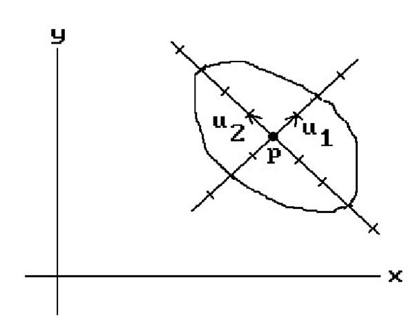
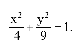
The Shape Coordinate System. This is the coordinate system used in the actual definition of a shape. It may very well be different from the world coordinate system. For example, the standard conics centered around the origin are very easy to describe. A good coordinate system for the ellipse in Figure 4.2 is defined by the indicated frame (u1,u2,p). In that coordinate system its equation is simply
Figure 4.2. A shape coordinate system.
The equation of that ellipse with respect to the standard world coordinate system would be much more complicated.
The Camera Coordinate System. A view of the world obtained from a central projection onto a plane is called a perspective view. To specify such view we shall borrow some ideas from the usual concept of a camera (more precisely, a pinhole camera where the lens is just a point). When taking a picture, a camera is at a particular position and pointing in some direction. Being a physical object with positive height and width, one can also rotate the camera, or what we shall consider as its “up” direction, to the right or left. This determines whether or not the picture will be “right-side up” or “upside down.” Another aspect of a camera is the film where the image is projected. We associate the plane of this film with the view plane. (In a real camera the film is behind the lens, whose position we are treating as the location of the camera, so that an inverted picture is cast onto it. We differ from a real camera here in that for us the film will be in front of the lens.) Therefore, in analogy with such a “real” camera, let us define a camera (often referred to as a synthetic camera) as something specified by the following data:
a location p
a “view” direction v (the direction in which the camera is looking)
an “up” direction w (specifies the two-dimensional orientation for the camera)
a real number d (the distance that the view plane is in front of the camera)
Clearly, perspective views are defined by such camera data and are easily manipulated by means of it. We can view the world from any point p, look in any direction v, and specify what should be the top of the picture. We shall see later that the parameter d, in addition to specifying the view plane, will also allow us to zoom in or out of views easily.
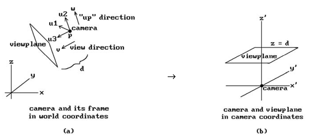
A camera and its data define a camera coordinate system specifed by a camera frame (u1,u2,u3,p). See Figure 4.3(a). This is a coordinate system where the camera sits at the origin looking along the positive z-axis and the view plane is a plane parallel to the x-y plane a distance d above it. See Figure 4.3(b). We define this coordinate system from the camera data as follows:
Figure 4.3. The camera coordinate system.
These last two axes will be the same axes that will be used for the viewport. There were only two possibilities for u1 in equations (4.1). Why did we choose![]() rather than
rather than![]() Normally, one would take the latter because a natural reaction is to choose orientation-preserving frames; however, to line this x-axis up with the x-axis of the viewport, which one always wants to be directed to the right, we must take the former. (The easiest way to get an orientation-preserving frame here would be to replace
Normally, one would take the latter because a natural reaction is to choose orientation-preserving frames; however, to line this x-axis up with the x-axis of the viewport, which one always wants to be directed to the right, we must take the former. (The easiest way to get an orientation-preserving frame here would be to replace![]() However, in the current situation, whether or not the frame is orientation-preserving is not important since we will not be using it as a motion but as a change of coordinates transformation.)
However, in the current situation, whether or not the frame is orientation-preserving is not important since we will not be using it as a motion but as a change of coordinates transformation.)
Although an up direction is needed to define the camera coordinate system, it is not always convenient to have to define this direction explicitly. Fortunately, there is a natural default value for it. Since a typical view is from some point looking toward the origin, one can take the z-axis as defining this direction. More precisely, one can use the orthogonal projection of the z-axis on the view plane to define the second axis u2 for the camera coordinate system. In other words, one can define the camera frame by
As it happens, we do not need to take the complete cross product to find![]() because the z-coordinate of
because the z-coordinate of![]() is zero. The reason for this is that
is zero. The reason for this is that![]() lies in the plane generated by
lies in the plane generated by![]() is orthogonal to
is orthogonal to![]() It follows that if
It follows that if![]() and
and then
then
It is also easy to show that![]() is a positive scalar multiple of
is a positive scalar multiple of (Exercise 4.2.1), so that
Although this characterization of u1 is useful and easier to remember than the cross product, it is not as efficient because it involves taking a square root.
Note that there is one case where our construction does not work, namely, when the camera is looking in a direction parallel to the z-axis. In that case the orthogonal projection of the z-axis on the view plane is the zero vector. In this case one can arbitrarily use the orthogonal projection of the y-axis on the view plane to define u2. Fortunately, in practice it is rare that one runs into this case. If one does, what will happen is that the picture on the screen will most likely suddenly flip around to some unexpected orientation. Such a thing would not happen with a real camera. One can prevent it by keeping track of the frames as the camera moves. Then when the camera moves onto the z-axis one could define the new frame from the frames at previous nearby positions using continuity. This involves a lot of extra work though which is usually not worth it. Of course, if it is important to avoid these albeit rare occurrences then one can do the extra work or require that the user specify the desired up direction explicitly.
Finally, given the frame![]() for the camera, then the world-to-camera coordinate transformation
for the camera, then the world-to-camera coordinate transformation![]() in Figure 4.1 is the map
in Figure 4.1 is the map
where M is the 3 x 3 matrix that has the vectors u as its columns.
We begin with a two-dimensional example.
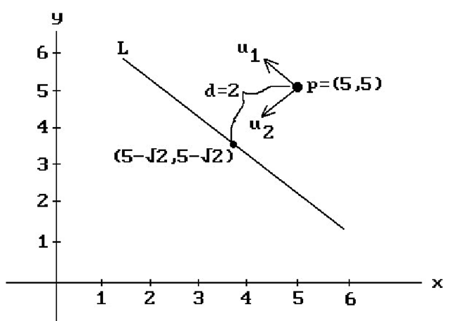
Example. Assume that the camera is located at p = (5,5), looking in direction v = (-1,-1), and that the view plane is a distance d = 2 in front of the camera. See Figure 4.4. The problem is to find
Solution. Let![]() . The “up” direction is determined by
. The “up” direction is determined by![]() in this case, but all we have to do is switchthe first and second coordinate of
in this case, but all we have to do is switchthe first and second coordinate of![]() and change one of the signs, so that
and change one of the signs, so that We
We
now have the camera frame It follows that
 is the map
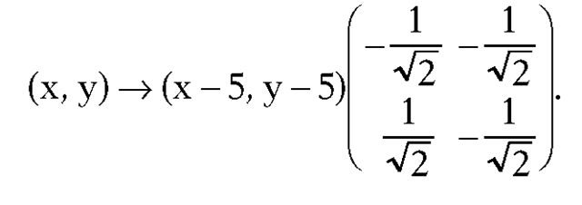
In other words,
Figure 4.4. Transforming from world to camera coordinates.
As a quick check we compute which clearly are the correct values.
Next, we work through a three-dimensional example.
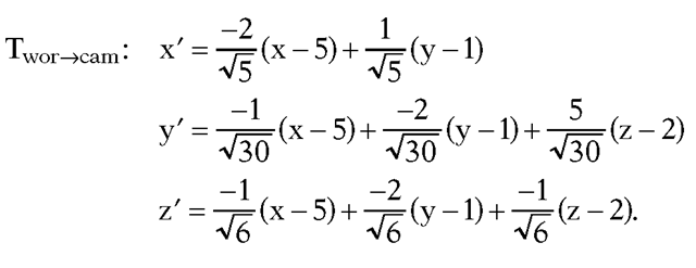
Example. Assume that the camera is located at p = (5,1,2), looking in direction v = (-1,-2,-1), and that the view plane is a distance d = 3 in front of the camera. The problem again is to find![]()
Solution. Using equations (4.2) we get
It follows that
Note in the two examples how the frame that defines the camera coordinate system also defines the transformation from world coordinates to camera coordinates and conversely. The frame is the whole key to camera coordinates and look how simple it was to define this frame!
The View Plane Coordinate System. The origin of this coordinate system is the point in the view plane a distance d directly in front of the camera and the x- and y-axis are the same as those of the camera coordinate system. More precisely, if (u1,u2,u3,p) is the camera coordinate system, then (u1,u2,p+du3) is the view plane coordinate system.
