30.6.
Supplementary Restraint System (SRS) or “Air-Bag”
The Supplementary Restraint System (SRS) is basically an air-bag system. This works together with conventional 3-point seat belts and prevents impact of the driver’s chest and face with the steering wheel in the event of a collision. SRS may sometimes be installed to the passenger’s side to prevent impact with the dashboard. Side-impact air-bags are also fitted to protect the upper body and head during a sideways impact.
At speeds in excess of 40 kmph the seat belt alone is no longer adequate in the event of a serious accident. Analysis after accidents has concluded that, in 68% of cases, an air-bag provides a significant safety measure. It is predicated that if all cars in the world are equipped with air-bags then the annual number of fatalities can be reduced by well over 50,000.
It is becoming popular to have an air-bag system with most of the required components placed in one unit. This reduces the amount of wiring and connection as well as improves the reliability. The operation of an air-bag cannot be tested as it only ever works once, therefore it is necessary to have some from of built-in monitoring system.
The SRS uses a gas-generator module, which contains an explosive charge. Therefore, on no account the SRS should be dismantled or tampered with. Also a multi-meter or oscilloscope should not be used to check the SRS connections and only the manufacturer’s dedicated diagnostic tester should be used with the SRS. Before scraping an SRS-equipped vehicle it is to be ensured that the air-bag has been deployed using the manufacturer’s deployment tool.
30.6.1.
SRS System Configuration
A typical SRS configuration is illustrated in Fig. 30.39, and the function of each component is listed in Table 30.2. The main components of an air bag system are :
• Driver and passenger air-bags. • A warning light.
• ‘ Passenger seat switches. • A pyrotechnic inflator.
• An igniter. • Crash sensor(s).
• An electronic control unit.

Fig. 30.38. Operation of rain sensor.
The system uses a number of deceleration sensors (D-sensors) installed at the front of the vehicle to sense the beginning of a frontal impact occurring within about 30 degrees of the vehicle centre line. An additional deceleration sensor (called a safing sensor or S-sensor) is installed in the passenger compartment and connected in series with the D-sensors. The S-sensor triggers at a much lower deceleration level than the D-sensor (2.5 g as against about 15 g), confirms occurrence of a collision and prevents firing of the air-bag due to localized impacts on the wings of the car.

Fig. 30.39. Major components of supplementary restraint system.
The sensor provides input signals into the SRS ECU often termed a “Diagnoistic Module”, which constantly checks and monitors the entire SRS. When a frontal collision is confirmed by both a D-sensor and the S-sensor, the diagnostic module sends a current pulse to fire a gas generator unit contained with the air-bag module, which is located in the steering wheel centre pad. The air-bag is then inflated. If the diagnostic module detects a fault with the SRS, an instrument panel warning lamp is illuminated and the SRS is deactivated to prevent accidental deployment. The driver should then take the vehicle for immediate repair.
30.6.2.
SRS Crash Sensors
The crash sensor used with the SRS varies with the system manufacturer, but all designs work on the same principle that they are open-circuit during normal driving and closed-circuit when subjected to a deceleration in the range 15 – 20g, corresponding to a 24 – 32 kmph impact with a solid object. Common designs include the magnetic bias sensor and the Rolamite sensor.
Table 30.2.
SRS Component Function.
| Component | Function | Remark |
| Air bag system warning lamp. | Lamp illuminates or flashes if malfunction occurs in air-bag system. | Located in instrument cluster. |
| Air bag module. | Deploys air-bag when current flows to integrate igniter. | Located in steering wheel hub. |
| Clock spring connector. | Ensures uninterrupted connection to air bag module while allowing turning of steering wheel. | Part of combination switch. |
| Crash sensor. | D-sensor: Activated (closed) when crash impact is detected, and with S-sensor, completes circuit to inflator. | Located in front part of vehicle (left, right and center). |
| S-sensor: Activated (closed) when crash impact is detected, and with D-sensor, completes circuit to inflator. | Located on side of heater unit in passenger compartment. | |
| Diagnostic module | Monitors components and wiring harnesses in air-bag system. Indicates system malfunction by flashing or illuminating air-bag warning lamp. If warning lamp is burnt, sounds warning buzzer. Detects short circuit between air-bag module and ground or crash sensor malfunction and melts system down fuse to prevent unintended air-bag deployment. |
Contains backup battery. |
Magnetic Bias Sensor.
This sensor (Fig. 30.40) uses a sensing mass (a metal ball) held firmly at the rear of a small cylinder by a powerful bias magnet. During normal driving the electrical contacts are open-circuit. When a collision takes place, the inertial force on the ball overcomes the magnetic bias force causing it to roll forward along the cylinder and to strike the electrical contacts thereby completing the detection circuit.
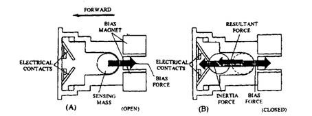
Fig. 30.40. Magnetic bias crash sensor. A. Normal condition (open). B. When impact occurs (closed).
Rolamite Sensor.
The Rolamite sensor (Fig. 30.41) uses a roll-spring, which is wrapped around a small roller and mounted to an electrical contact pad. The roll-spring is pre-tensioned so that during normal driving the roller is held firmly against a backstop and the detector contacts are open-circuit. When a collision occurs, the inertial force on the roller overcomes the
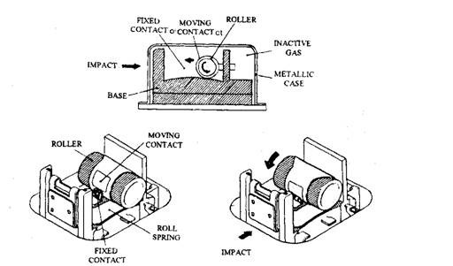
Fig. 30.41. Rolamite-type crash sensor.
pretensions on the roll-spring, due to which it travels forwards until the electrical contacts meet, completing the detection circuit.
The total system is housed in airtight metal enclosures that are filled with inert gas to prevent corrosion and to ensure the mechanical and electrical functions of the crash sensors. Each sensor is wired as a normally-open switch, but with a resistor connected in parallel with the contacts. The resistor permits the diagnostic module ECU to continually monitor the circuit’s continuity for connector and wiring defects.
30.6.3.
Rotary Coupler, Air-bag and Inflator
The air-bag and inflator are located in the steering wheel centre pad and connected to the diagnostic module by a clock-spring electrical rotary coupler, fitted between the steering wheel and steering column housing. The air-bag is a woven nylon bag, which is lined with rubber and
folded-up behind a plyurethane cover (Fig. 30.42). As the bag is inflated, the cover tears along the crease and hinges open. This causes the bag to deploy. A fully inflated bag has a gas capacity of between 30 and 70 litres, depending upon the vehicle size.
Figure 30.43 illustrates the detailed construction of the inflator unit. Inflation takes place when the diagnostic module sends a current pulse to the ‘squib’ igniter. Both electrical connections to the igniter are floating [i.e. isolated from the vehicle ground) to avoid firing by an accidental short circuit.
Once the igniter attains a temperature of over 463 K self-ignition of the mixture takes place. The generated heat causes the sodium azide propellant pellets to undergo rapid combustion, generating nitrogen gas, which is filtered and
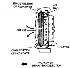
Fig. 30.42. Section through air-bag module.
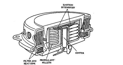
Fig. 30.43. Section through inflation air-bag unit.
cooled before passing into the air-bag. The bag’s internal pressure, when fully inflated is about 10<o 30 kPa, which is comparatively two but sufficient to safeguard the driver if dashed against it. The drivers thrust on the air-bag pushes gas to escape through two large outlet holes in the rear of the bag to further cushion the impact.
30.6.4.
Diagnostic Module ECU
Reliability is a prime requirement of the air-bag system. It must fire within a few milliseconds, even after many years of inaction. The diagnostic module therefore ensures that the SRS is always in a state of readiness. This is met by monitoring the firing and sensor circuits and indicating faults through the SRS warning light. Fault data is stored in non-volatile memory for future reference. The cash sensor signals are processed causing the firing of the igniter when a frontal impact is detected.
To ensure no failure of electrical power during an early stage in the collision, SRS diagnostic modules incorporate some form of power storage. Normally an initial backup battery or a large-value capacitor is kept charged-up to provide about 200 ms of reserve power, sufficient to fire the inflator.
30.6.5.
Pyrotechnic Seatbelt Tightening System
The pyrotechnic seatbelt tightening system that complements an SRS system uses similar technology and operating principle (Fig. 30.44). Its function is to tighten the seatbelt around the driver and front passenger for holding them safely and firmly into their seats in the initial few milliseconds after an impact.
A cable which is wrapped around the inertia-reel seatbelt drum is used to tighten the belt. The free end of the cable is connected to a piston sitting at the bottom of tube mounted in the car’s B-post. An explosive capsule containing a detonator and propellent is placed beneath the piston. A crash sensor, fitted under the front seat, triggers to fire the detonator when a frontal deceleration of 5g or move is sensed. The system provides detonation within about 15 ms of impact, causing the piston to move up the tube. This movement of the piston pulls the cable, which rotates the drum and removes about 10 cm of slack from the seatbelt.
30.6.6.
SRS and Pyrotechnic Seatbelt Deployment Sequence
Figure 30.45 illustrates the timing of SRS and pyrotechnic seat deployment. The sequence of operation is typically as follows:
(i) Time = 0 ms. Collision of the vehicle takes place at an angle within about 30 degrees of the centre line and at a speed greater than about 32 kmph.
(«) Time = 10 ms. The front crash sensors and the safing sensor have moved to the closed-circuit position, causing the SRS diagnostic module to transmit a firing pulse to the igniter. The pyrotechnic seatbelt unit has detonated.
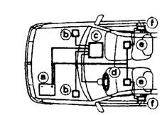
Fig. 30.44. Combined air-bag and pyrotechnic seatbelt crash protection system.
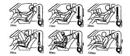
Fig. 30.45. Timing of air-bag and pyrotechnic seatbelt deployment.
(Hi) Time = 13 ms. After 3 ms of the arrival of the igniter firing signal, gas generation has started with a loud bang. The driver is still upright in his seat. The seatbelt has been partially tightened.
(iv) Time = 15 ms. The air-bag has partially inflated, breaking the cover crease. The seatbelt is almost fully tightened.
(v) Time = 20 ms. The vehicle is starting to crumple and the driver has moved very slightly forward towards the steering wheel but is being restrained by the seatbelt which is how fully tightened.
(vi) Time m 30 ms. The air-bag is fully inflated and the driver’s chest and face are about to come into contact with it. The seatbelt is helping to restrain the driver.
(vii) Time = 80 ms. The load of the diver on the air-bag causes the nitrogen gas to escape through the outlet holes at the rear of the bag due to which it starts to deflate. Gas pressure beneath the pyrotechnic seatbelt piston is falling and so it starts to move back down the tube, feeding some slack back into the belt.
(viii) Time = 120 ms. The driver has moved back into his seat and the air-bag is deflating, providing unrestricted visibility and permitting an easy exist from the wrecked vehicle.
At the end of the deployment, the interior of the vehicle is found covered with a small amount of white power residue from the air-bag inflator. This is mostly sodium carbonate (Na2CC>3), and a tiny amount of sodium hydroxide (NaOH), neither of which is hazardous.
30.6.7.
Single-module SRS
Some vehicle manufacturers are using air-bag systems where all of the SRS elements are integrated, including the cash sensors, into a single module installed within the steering-wheel centre cover. These systems have minimum number of connectors and optimum length of wiring, improving reliability and reducing cost.
30.6.8.
Side-impact Air-bags
The side-impact air-bags were used first during mid 1990, to protect occupants in the event of a sideways collision of the vehicle. In general the system uses a 17 litre air-bag module installed in each door panel and additional inflatable tubes installed along the roof rails. A normal frontal SRS air-bag system safeguards the driver by cushioning the secondary impact with the steering wheel during a frontal impact, whereas the side-impact air-bag gently accelerates a occupants into the centre of the vehicle and thereby prevent contact with the door panel. Side-impact air bags therefore work at a higher inflation pressure, and deflate more slowly than frontal-impact air-bags.
Each side-impact air-bag inflator is coupled to a diagnostic unit, which operates in the same way as a frontal SRS ECU. Triggering of the side-impact air-bag is commenced by lateral acceleration sensors, which detect any sudden change in the side-ways movement of the vehicle. These sensors are similar to that of the crash sensors used in an SRS system, although the mounting orientation is different and the trigger level is set at lower ‘g1 level.
