30.5.
Electric Seats, Mirrors and Sun Roof Operation
Electric movement of seats, mirrors and the sun roof is quite similar. Basically all of these are operated through one or several permanent magnet motors, along with a supply reversing circuit. A typical motor reverse circuit is illustrated in Fig. 30.31. When the switch is operated, one of the relays operates and changes the polarity of the supply to one side of the motor. In the same way if the switch is moved in the other direction, the polarity of the other side of the motor

Fig. 30.30. Pressure wash-system with a retractable nozzle.
is altered. When the motor is stopped both sides instantly attain the same potential, which has the effect of regenerative braking. Additional refinements have been introduced to improve the operation of these systems. Limit switches, position memories and force limitation are the most common features.
Table 30.1. Fault-diagnosis Chart for Central Door-locking System
Electric Seat Adjustment
Seat adjustment is carried out through positioning of different parts of the seat using a number of motors. Movement is achieved in the following ways :
• Front to rear. • Rear cushion height.
• Front cushion height. • Backrest tilt.
• Headrest height. • Humber support.
Figure 30.32 represents a typical electronically controlled seat, which uses four positioning motors and one smaller for a pump used to control the lumber support bag. Each motor is normally operated by a simple rocker type switch, which controls two relays to change the polarity of supply as described above. Nine relays, therefore, are used, two for each motor and one to control the main supply.
Once the seat position is set some vehicles use set position memories for automatic repositioning, when the seat has been moved. This arrangement is often combined with electric mirror adjustments. Figure 30.33 demonstrates the circuit for position memory. As the seat is moved, a variable resistor mechanically linked to the motor also moves and the value of the resistance provides feedback to an electronic control unit. One of the techniques used in the position memory is to supply the resistor with a fixed voltage such that the output relative to the seat position is proportional to the position. This voltage is then converted from analogue to digital form producing a simple number, which is stored in a digital memory.
If the memory recall switch is pressed, the ECU activates the motor relays until the number in memory and the fed back number from the seat are equal. This facility is normally isolated during operation of the engine to avoid movement of the seat to any dangerous position as the car is being driven. However the positions of the seats can still be adjusted by operating the switches as normal. Seat heaters are often used with this type of system.
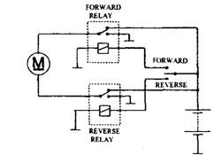
Fig. 30.31. Motor reverse circuit.
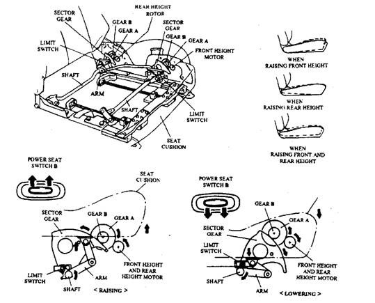
Fig. 30.32. Electrically controlled seat.
30.5.2.
Electric Mirrors
Now-a-days many vehicles incorporate electrical adjustment of mirrors, specifically on the passenger side as it is difficult for the driver to reach for adjusting the door mirrors. Each mirror assembly contains an enclosure, fixed to the door frame, and a mirror-glass, which pivots on a nylon ball-joint. The system used is much the same as that used for seat movement. The mirror is moved vertically and horizontally by two small motors. Many mirrors also incorporate a small heating element on the rear of the glass. This is operated for a few minutes when the ignition is initially switched on. This can also be linked to the heated rear window circuit. An electrically operated mirror circuit, using feedback resistors for positional memory is shown in Fig. 30.34.
30.5.3.
Electric Sun Roof Operation
Although an electric sun roof also works on the motor reverse circuit, the system incorporates additional components and circuit to allow the roof to slide, tilt and stop in the closed position. The extra components required are a micro-switch and a latching relay. A latching relay works in much the same way as a normal relay, except that it locks into position each time it is activated. To achieve this, the mechanism used is much similar to the ball point pens that use a button on top. The micro-switch is mechanically positioned and operated when the roof is in its closed position. A rocker switch permits the driver to adjust the roof.
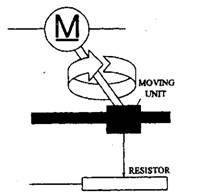
Fig. 30.33. Position memory for electric seats.
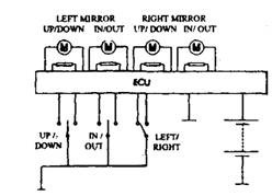
Fig. 30.34. Feedback resistor for positional memory and the circuit.
Figure 30.35 illustrates the circuit for an electrically operated sun roof. The switch allows the motor to run in the chosen direction to open or tilt the roof. To close the roof, the motor is run in the appropriate direction until the micro-switch closes while the roof is in its closed position. This causes the latching relay to change over to stop the motor. Now the control is released. Once again if the switch is pressed, the latching relay again changes over to run the motor.
30.5.4.
Electronically Dipped Rear View Mirror
The electrically dipped rear view mirror automatically darkens when strong light falls on the mirror glass. It therefore, protects the driver from the glare of following headlights when travelling at night. This mirror uses special electro-chrome (EC) glass, the reflectivity of which can be controlled electronically. Due to the absence of any moving part, the system operates noiselessly and does not alter the angle of the
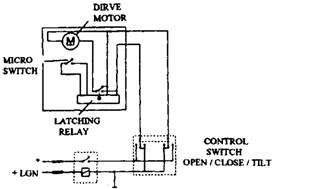
Fig. 30.35. Circuit for an electrically operated sun roof.
mirror glass. A block diagram of the EC mirror glass and associated electronics is shown in Fig. 30.36. Two photosensitive resistors are used to determine the lighting levels. One photo resistor faces the rear window and senses the light level falling on the mirror glass. The other photo resistor faces the windscreen and senses the ambient light level seen by the driver. Based on the difference between these two light levels a differential amplifier module produces an output. The electronic module applies a bias voltage to the mirror electrodes when the light level falling on the rear-facing sensor exceeds a certain percentage of the ambient light level. This voltage causes a flow of ions from the electrolyte into the front electrodes, which darkens the EC glass thereby reduces the amount of light reflection from the mirror. The amount of darkening is proportional to the bias voltage, and hence it is dependent on the difference in light levels falling on the two sensors
The alteration is mirror reflectivity takes place slowly. The dimming time (from 70% to 20% reflectance) is about four seconds, and the restoring time (from 10% to 60% reflectance) is around seven seconds. When reverse gear is engaged, an override input from the reversing light switch disables the dimming function.
Figure 30.37 illustrates the arrangement of the electrically dipped mirror. The sensors and electronic module are placed inside the mirror casing and a control is incorporated to vary the sensitivity or to switch off the dipping function.
30.5.5.
Rain Sensor
Although variable windscreen-wiper delay allows the adjustment of the wiper operating interval to suit the amount of rainfall, however it is often necessary to make frequent adjustment
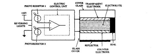
Fig. 30.36. Electro-chrome mirror glass and control electronics.
due to variation of the weather or road conditions. During light rain-fall, a rain sensor continuously monitors the amount of rain striking the windscreen. A microcomputer-based ECU processes the sensor signal and alters the wiper delay interval suiting to the rain intensity.
The rain sensor is installed inside the car behind the rear view mirror and works on the principle of reflection of infrared light from the windscreen (Fig. 30.28), Light from an infrared transmitter diode is focused through a lens and then coupled to the windscreen through a light
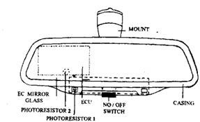
Fig. 30.37. Practical arrangement of EC dipping rear view mirror.
guide, which is bonded to the glass with a transparent adhesive.
When the windscreen is completely dry, the most of the light is reflected from the outer surface of the glass, which returns through the light guide to a second lens to focus the rays onto the receiver diode. On the other hand, when rain falls onto the windscreen, some of the transmitted light due to refraction is lost from the system into the raindrops, so that they do not reach the receiver. This causes a loss of signal which the ECU interprets as a particular level of rainfall, which is referred as to adjust the wiper delay interval appropriately.

