28.9.
Servo Operation
If the force applied comfortably by a driver to the footbrake is insufficient to retard the vehicle at the required rate, some form of assistance is necessary. The boosting force applied to supplement the driver’s effort is called servo assistance.
In the past servo assistance was provided by rotation of the brake drum (self-servo) to keep the pedal force low. Today due to introduction of powerful disc brakes, the servo assistance is provided by either pneumatic or hydraulic means. In practice, vacuum assistance is added for medium cars, hydraulic assistance for heavy cars and vehicles fitted with anti-lock braking systems, and compressed-air assistance for some light trucks and minibuses.
28.9.1.
Vacuum Assisted Servo
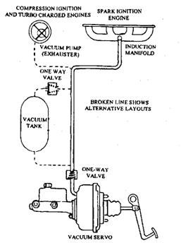
This servo system is the most popular. The induction manifold depression of the spark-ignition engine is used as source of servo energy in most systems. Since vacuum energy is not available at the manifold of a diesel engine, an engine-driven ‘vacuum’ pump (exhauster) in this case provides the required assistance.
All servo systems must be fail-safe, i.e. if a fault develops in the vacuum unit the main braking system must be operative, however with a pedal force much greater than normal. The operation of the servo should be progressive, i.e. the servo assistance should be proportional to the pedal effort for light pedal pressure. Figure 28.50 represents the relationship between the hydraulic pressure acting on the brake cylinders and the pedal effort for both with and without servo assistance. The servo valves provide a progressive assistance up to the knee point where the maximum vacuum assistance is received and any rise in output pressure beyond this point is only due to the increased pedal effort.
Vacuum servos in use today are called suspended-vacuum systems, because ‘vacuum conditions’ prevail on both sides of the servo piston during operation of the vehicle with the brakes off. When the brake is applied, outside air is bled in to the chamber on one side of the piston to create a pressure difference. This arrangement allows the servo to respond quickly in comparison to the older atmospheric suspended type system. In this older system, air is present on both sides of the piston and the air is ‘drawn out’ to provide assistance. The two main types of suspended-vacuum servos are the indirect and direct type.

Fig. 28.50. Servo assistance.
Indirect Servo System.
Indirect type is mounted remote from the pedal in the hydraulic line between the single master cylinder and the wheel cylinders, and hence is also called as remote type. A servo suitable for a medium-sized car (Fig. 28.51) uses of three main components :
(a) Vacuum cylinder containing a spring-loaded diaphragm.
(b) Slave hydraulic cylinder.
(c) Control valve actuated by hydraulic pressure.

Fig. 28.51. Suspended-vacuum servo-indirect type.
When the engine is running with the brake off, the vacuum valve remains open so that equal ‘vacuum’ pressure is applied on both sides of the diaphragm (Fig. 28.51A). As the brake pedal is applied, hydraulic pressure acts on the brakes and also raises the valve piston in the servo, so that the vacuum control valve is closed and the air valve is opened. Air is bled in to break the ‘vacuum’ in the outer chamber of the vacuum cylinder. The difference in air pressure causes the booster diaphragm to apply a thrust on the slave-cylinder piston, which in turn boosts the effort provided by the driver (Fig. 28.51B). ‘Proportional’ braking is achieved by suitably adjusting the difference in air pressure felt by the booster diaphragm. As the difference in pressure increases, the diaphragm overcomes the hydraulic pressure acting on the valve piston and closes the air valve (Fig. 28.51C). When the pedal is released, the hydraulic pressure drops causing the valve piston to return and the vacuum control valve to open. Air is quickly evacuated from the outer chamber of the vacuum cylinder so that a spring returns the diaphragm.
When the servo fails, a hole in the centre of the slave-cylinder piston ensures the operation of the brake. Apart from general inspection of hoses etc. the unit requires periodic cleaning of the air filter. The indirect type has become obsolete, because of the popularity of a tandem-operated hydraulic system.
Direct Servo System.
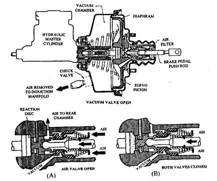
The direct-acting suspended-vacuum servo can be used with either single or tandem master cylinders. It is directly connected to the pedal linkage. The unit, shown in Fig. 28.52, illustrates the situation when the engine is running, the brakes are ‘off and the servo piston is ‘suspended
in vacuum’. Air has been removed from both servo compartments and passed to the engine manifold through the pipe and non-return valve installed adjacent to the vacuum chamber. Air is evacuated from behind the rubber-diaphragm-sealed piston using a control valve linked to the footbrake pedal.

Fig. 28.52. Direct-acting servo. A. Brake being applied or fully applied. B. Brake held on.
As the brake pedal is pressed, the vacuum valve is closed first and then the air valve is open (Fig. 28.52A). Consequently air flows through the filter and valve to the rear chamber. Difference in air pressure between the two chambers produces a force on the piston, which boosts the effort applied by the driver. Movement of the servo piston applies a force on the master cylinder push-rod through a rubber reaction disc. Because of pressure, this spongy disc squeezes back and closes the air valve (Fig. 28.52B). At this stage the driver’s efforts are supplemented by a servo boost, proportional to the effort applied. The driver is also able to ‘feel’ the load applied to the brake progressively.
Further movement of the pedal re-opens the air valve so that the previous events are repeated up to the ‘knee point’. Beyond this point the driver can keep the air valve open, as the servo assistance has reached its maximum limit. Release of the brake pedal closes the air valve and opens the vacuum valve. This restores the vacuum suspension of the piston so that the spring returns the piston to the ‘off position. In case of vacuum failure the brakes can still be applied without servo assistance. The assistance provided by a vacuum chamber is proportional to the area of the piston and therefore it increases with the increase of the area. Since it is difficult to accommodate a very large cylinder adjacent to the footbrake on a modern car, various systems are incorporated to overcome this problem. One arrangement is to fit a servo cylinder with two pistons mounted in tandem.
Even though many servo units are operated directly from the induction manifold, to improve performance and for extra safety a vacuum reservoir is used to ‘store vacuum’ (Fig. 28.53). In case of a diesel engine a separate engine driven pump is incorporated for servo assistance. This vacuum pump, or exhauster, produces a vacuum to about 66.5 to 80 kPa (500 – 600 mm of mercury).

Fig. 28.53. Vacuum servo layout.
28.9.2.
Hydraulic Assisted Servo
Since the pressure difference of a vacuum assisted servo arrangement is limited, a system to provide a much greater source of energy is necessary to stop a heavy motor car or light truck. This is achieved by incorporated a hydraulic servo, which operates on a pressure range of 5295 to 8842 kPa. The hydraulic power produced by the engine-driven pump of this system can also be used to provide for other servo needs, e.g. power-assisted steering, lifts, etc.
Figure 28.54A illustrates a continuous-flow hydraulic servo system. A multi-cylinder pump, driven from the engine or transmission, supplies fluid to the servo valve, mounted behind the conventional master cylinder. The brakes are in the ‘off position in the diagram, when the fluid can easily pass between the master-cylinder piston and servo valve to a drilling connecting the reservoir.
Depression of the brake pedal first closes the conical servo valve due to which the pump builds up a pressure in the region A, so that the piston and valve are forced apart. The piston has a larger area than the valve, so that greater thrust is exerted on the piston than that acting on the valve and brake pedal. This area ratio determines the servo assistance that can be provided to the driver. Once a predetermined pressure is reached the servo valve opens partially to maintain the pressure and provide assistance. When the pedal force become high, a pressure relief valve opens, which allows fluid to escape to the reservoir. Release of the brake pedal opens the servo valve, releases the brakes, and restores uninterrupted flow of fluid from the pump to the reservoir.

Fig. 28.54. Hydraulic-servo systems.
A. Continuous flow system without accumulator.
B. Continuous flow system with accumulator.
Continuous-flow System with Accumulator.
Since the assistance provided by the continuous-flow system depends on the pump speed, a ‘hard’ pedal is felt whenever the pump is stationary or rotating slowly. This problem is overcome by incorporating a hydraulic accumulator or pressure storage cylinder into the system (Fig. 28.54B). The accumulator uses a spring-loaded piston or air bag, which is acted upon by the fluid. Hence, higher the fluid pressure, the more the bag or spring is compressed. A cut-out valve is installed to maintain the accumulator pressure in the range of 5395 to 8842 kPa. A charging valve is operated by fluid pressure from the output or brake line side of the master cylinder, and supplies fluid from the accumulator to act on the servo valve when the pump fails to supply the required fluid. It is essential to discharge and drain the accumulator before any part is disconnected from this system.
28.9.3.
Compressed-air Assisted Servo
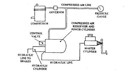
An alterantive to the hydraulic servo, used on light trucks and minibuses, is a compressed-air servo. The layout of the system is shown in Fig. 28.55. This is also known as air/hydraulic (air over hydraulic) or Airpac system as compressed air is used to boost the force applied by the driver to a hydraulically operated brake. Air pressure is generated by a engine-driven compressor, and is stored in a reservoir adjacent to the servo chamber. The servo chamber houses a piston. This piston operates another piston that controls the main hydraulic brake line. During application of the brake, a valve supplies the compressed air into the servo cylinder to boost the pedal effort.

Fig. 28.55. Basic layout of air I hydraulic system.
