28.10.
Anti-lock Braking Systems (ABS)
28.10.1.
Need for an Anti-lock System
It is difficult to assess the required brake pedal force to be applied for an emergency stop in the shortest possible distance. This is because it is practically impossible to take into account several varying factors such as type and roughness of the road and tyre, and the condition of the road surface. Consequently, in the extreme case, the driver applies either too much or too little pressure on the pedal causing the following effects.
(i) Pedal pressure too high. One or more of the wheels skid over the surface so that: (a) Stopping distance is increased. This is due to the fact that the adhesion between a
skidding wheel and the road is less than when a wheel is on the verge of skidding. (6) Directional control is jeopardized. If a rear-wheel skid occurs, then the vehicle turns
towards the rear.
(«’) Pedal pressure too low. Stopping distance is increased. This can cause an impact with an obstacle.
Adhesion between the road wheel and road surface depends on the coefficient of friction. This varies considerably with changes in the condition of the road surface (Table 28.1). On a dry
surface the adhesion varies as the wheel slip changes from 0 percent (no slip) to 100 percent (locked wheel sliding over the surface). Figure 28.56 illustrates the variation of the longitudinal and transverse adhesion of a tyre on a typical surface as the amount of slip increases. The longitudinal adhesion curve for a given condition indicates that a braking force on a wheel set for about 15 percent slip provides the maximum retarding force. The transverse adhesion curve shows the vehicle stability with respect to its tendency to slide sideways. The adhesion in this direction falls just after the wheel starts to skid. Therefore, any serious skidding can soon lead to

Fig. 28.56. Adhesive force and wheel slip.
loss of control, especially if the driver is making a steering correction, or if the vehicle is cornering. In the mid-1980s various skid-limiting arrangements were added to the braking systems and these systems are generally called anti-lock brake systems (ABS).
28.10.2.
Types of ABS
The basic requirements of an anti-locking system are to retain steerability in maximum braking situations and to avoid danger of skid under all road conditions. In addition, the system should be fail-safe and low in weight. The anti-lock braking systems in use differ in their method of sensing wheel slip, for which both electronic and mechanical methods are in use.
28.10.3.
Electronically Sensed ABS
The early electronic ABS units were designed as ‘add-on’ systems. The latest generations of electronic systems are built into the hydraulic brake circuit forming an integrated brake system. The master cylinder and vacuum servo used in the braking system have been replaced by a hydraulic pump-assisted braking unit. This arrangement provides normal braking as well as anti-lock functions.
Electromagnetic sensors are used for skid sensing of each wheel. These sensors record and communicate any rapid change in speed of rotation, i.e. the percentage slip of the wheel, to an electronic control unit (ECU).
System Layout.
The arrangement of the main components of a four-wheel regulated ABS similar to that made by ATE is shown in Fig. 28.57. The system contains both hydraulic and electronic subsystems.

Fig. 28.57. ABS layout (ATE).
Hydraulic Sub-system.
This subsystem is built as an integral unit in modular form around a driver-controlled master cylinder (Fig. 28.58) for normal and anti-lock functions. A hydraulic booster, which is fed with pressurized fluid (between 13730 and 17660 kPa) from an electrically driven pump, is installed at the end of the master cylinder. An accumulator stores the pressure and also smoothes the output pulses from the pump. Control of the pressure in the two hydraulic lines to front brakes as well as the lines connecting to two rear brakes is through valves installed in a modulator unit.
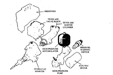
Fig. 28.58. ABS integrated hydraulic unit (ATE).
Electronic Sub-system.
The electrical layout is shown in Fig. 28.57. A sensor, attached to each wheel, detects the speed of movement of a toothed gear wheel that is driven by either the drive shaft or the road wheels. Although it is designed for a four-wheel sensed system, the rear wheels are regulated as a pair. When a rear wheel sensor detects the onset of a skid, then fluid pressure to both wheels is reduced. This is called a select-low operating principle, as the pressure acted on to both wheels is dictated by the wheel having the lowest adhesion.
The sensors transmit the signals to an ECU.
Two microprocessors, incorporatsd in the control system, compare the input signals received from each wheels with those obtained previously. When a wheel starts to skid, an output signal actuates a return valve, which releases the pressure slightly in that particular hydraulic line. The ECU monitors about 8000 sensor signals per second and takes appropriate action within a few milliseconds, to provide a lock-free state of all wheels ensuring safe deceleration and good vehicle stability.
Warning lamps signal any fault in the pressure and electrical sections of the ABS. The system is monitored through self-checking electrical pulses that are continually passed around the circuit and valves. When a defect is detected, the anti-lock mechanism is automatically set in the fail-safe mode. A lamp signals this information to the driver.
Three phases of operation take place in a triple fluid circuit system of an anti-lock brake having one pair of solenoid valves per circuit. These include :
(i) pressure reduction phase,
(ii) pressure maintenance phase, and (Hi) pressure increase phase.
The input and return valves in each fluid circuit control these phases and provide the maximum braking force without exceeding the skid limit for the prevailing road conditions. An ABS layout using a dynamic flow principle is shown schematically in Fig. 28.59. In this type of system the fluid is pumped continuously around the circuit. The output from the pump passes through the hydraulic booster and then through the master cylinder before it is returned to the pump input for recirculation.
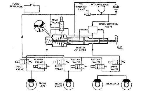
Fig. 28.59. Schematic diagram of an ABS layout.
Pressure Reduction.
When a sensor signals the starting of a wheel skidding, the ECU closes the input valve and opens the return valve in the valve block. This causes reduction in fluid pressure in the appropriate line so that the risk of wheel locking is reduced. The surplus fluid coming from the return valve passes to the reservoir.
To commence operation of the ABS, the ECU opens the main valve, so that pressurized fluid in the booster chamber flows over the cup seal of the master cylinder into the pressure chamber in the forward part. This replenishes the fluid returned to the reservoir by the return valve as well as provides both front brake circuits with a pressure proportional to the pedal force. During normal brake operation, the fluid from the booster circuit passes to the rear brakes at a pressure proportional to the pedal force. For ABS regulation of the rear wheels, the single return valve in the line reduces the pressure equally for both rear wheels based on select-low operating principle.
Pressure Maintenance.
Once the drop is fluid pressure is sufficient to avert wheel locking, the ECU closes the return valve to maintain the pressure.
Pressure Increase.
When the sensor signals about free running of the wheel, an input valve in the regulated fluid line is opened to increase the pressure up to a point where the percentage slip is greater than required. This regulated cycle is repeated about 12 times per second. At this frequency the vibration of the wheel and suspension assembly is avoided.
Regulation Cycle.
Figure 28.60 illustrates the sequence followed by an ABS when a vehicle retards at its maximum rate. The braking action on one wheel of the vehicle is represented by the simplified curves. The figure indicates the control of the valves which allow the braking force to be varied to maintain the wheel within the slip limits dictated by the prevailing conditions. Action of ABS varies the speed of the wheel. The points A, B, and C marked on the graph indicate the three phases of the operation. At point A, brake pressure is reduced by a specified amount, at point B it is held constant allowing the wheel to accelerate, and at point C it is again increased until the designed slip limit is reached.
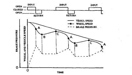
Fig. 28.60. Regulation cycle.
28.10.4.
Mechanically Sensed ABS
This system was introduced by Lucas-Griling, and was offered as an ‘add-on’ for the Ford Escort. Being called as a mechanical system, it senses the adhesion of the front wheels with the help of two modulator units that are driven by belt from the front drive shafts. Figure 28.61 shows the layout of this system in which the ABS modulator unit is located in the diagonally split fluid circuit between the master cylinder and the wheels.
The modulator units regulate the braking effort on diagonally disposed wheels so that when one side is more slippery than the other, one rear wheel still holds its grip. This maintains the car on a straight path even though the diagonally opposite front wheel has not been acted upon by its anti-skid modulator. Once a modulator detects the slip, the normal three phases of ABS regulation, i.e. release, maintain and apply are followed. \j
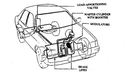
Fig. 28.61. Lucas-Girling stop control system (SCS).
Modulator.
The modulator uses mechanically driven pump and dump valve. The valve is triggered by a slip-sensitive flywheel and clutch arrangement. The ‘free-running’ flywheel is driven by a toothed belt at a proportionally faster speed than the adjacent front wheel, and it detects any rapid changes in wheel speed, if a wheel begins to skid. When the drive is taken through a ball ramp, the speed difference between the flywheel the driving shaft causes the flywheel to move sideways so that a fluid dump valve is operated. Figure 28.62 represents the modulator that is set in the normal braking position.
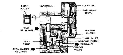
Fig. 28.62. Mechanically sensed modulator (Lucas-Girling).
28.10.5.
Traction Control System (TCS)
The electronic sensing system incorporated in ABS for the detection of slip can also be used to control and limit the maximum traction force utilized for the vehicle propulsion. This arrangement was first introduced by Harry Ferguson in 1954. The control is achieved by blocking the compensating function of the differential in certain driving situations by using a computer. This partial differential locking action is obtained by using ABS components to provide a braking action on a skidding wheel. When both driving wheels undergo excessive slip, the ECU in addition to acting upon the brakes, alters the engine throttle setting to reduce the driving torque. Some of the new generation ABS layouts are designed to easily accommodate a TCS module.
