16.4.
Programmed Ignition
16.4.1.
General Description
The term programmed ignition is used by Rover and some other manufacturers. Ford, Bosch and some others name it electronic spark advance (ESA). Constant energy electronic ignition is commonly used in countless applications. Its limitations, however, lies on the dependence upon mechanical components for speed and load advance characteristics. In many cases these did not match ideally the requirements of the engine.
Programmed ignition systems operate digitally, which is the major difference compared to earlier systems. In this system sensed information regarding the operating requirements of a particular engine can be programmed into memory of the electronic control unit. The data for storage in read only memory (ROM) is obtained from rigorous testing on an engine under various operating conditions. Programmed ignition has several advantages as follows :
(i) The ignition timing can be accurately matched to the individual application under a
range of various operating conditions.
(ii) Control inputs like coolant temperature and ambient air temperature can be used.
Other inputs such as engine knock can be taken into account.
(Hi) Starting is improved, fuel consumption as well as emissions are reduced, and idle control is better.
(iv) The number of wearing components is considerably reduced in this system.
Programmed ignition or ESA can be installed as a separate system or included as part of the fuel control system. This provides numerous possibilities in the management of the engine control.
16.4.2.
Sensors and Inputs
The layout of the Rover programmed ignition system is shown in Fig. 16.50. Certain input information is required by the ECU to calculate suitable timing and dwell outputs.

Fig. 16.50. Layout of the Rover programmed ignition system.
Crankshaft Sensor for Engine Speed and Position.
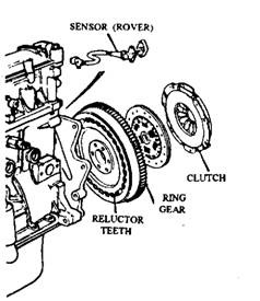
The crankshaft sensor is a simple reluctance sensor (Fig. 16.51), which is consisted of a permanent magnet, a winding and a soft iron core and is mounted close to a reluctor disc. The disc has 34 teeth spaced at 10 degrees intervals around the periphery of the disc and has two teeth missing at 180 degrees, and at a known position before TDC. This technique, with minor changes is used by many manufacturers. When a tooth of the reluctor disc passes the core of the sensor the reluctance of the magnetic circuit is changed, which induces a voltage in the winding, because the frequency of the wave form is proportional to the engine speed. The missing tooth causes a missed output wave, which is used to determine engine position.
Manifold Absolute Pressure Sensor for Engine Load.
Since engine load is proportional to manifold pressure, high load conditions produce high pressure and
lower load conditions such as cruise produce lower pressure. Load sensors are therefore pressure transducers and are either mounted in the ECU or as a separate unit. They are connected to the inlet manifold with a pipe. The pipe often has a restriction to damp out fluctuations and a vapour trap to prevent petrol fumes reaching the sensor.
Engine Coolant Temperature Sensor.
Coolant temperature measurement is carried out by a simple thermistor, which is also used, in many cases, for the operation of the temperature gauge and to provide information to the fuel control system. The basic timing settings are corrected using a separate memory map.
Detonation (Knock) Sensor.
An engine may face serious damage due to combustion knock or detonation if subjected for long periods. The over-advanced ignition timing causes this knock. On the other hand, an engine in general runs most efficiently when the timing is advanced as far as possible. To achieve this, the basic timing map should provide the data as close to the knock limit of the engine is possible (Fig. 16.52). The knock sensor provides a margin for error. The sensor is often of the piezo-electric type ac-celerometer and fitted in the engine block between cylinders two and there on in-line four-cylinder engines. V-engines require two sensors, one on each side. The ECU receives the signals from the knock sensor in the engine’s knock window for each cylinder. This is often just a few degrees each side of TDC. This prevents clatter from the valve mechanism being interpreted as knock. If detonation is detected, the ignition timing is retarded on the fourth ignition pulse in four-cylinder engine in steps until knock is no longer detected. A 2 degrees step is typical although the steps vary between manufacturers. The timing is then advanced slowly in steps of less than 1 degree over

Fig. 16.51. Reluctance engine speed and position, crankshaft sensor.

Fig. 16.52. Knock limit of an engine.
a number of engine revolutions, until the advance required is restored. This fine control allows the engine to be run very close to the knock limit without risk of engine damage.
Battery Voltage.
A lower voltage supply to the coil requires a slightly higher dwell figure, therefore correction to dwell settings becomes necessary when the battery voltage falls. This information is often stored in the form of a dwell correction map.
16.4.3.
Electronic Control Unit
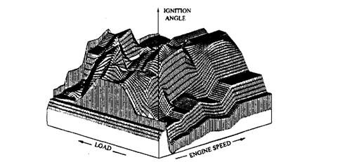
With the increase of sophistication of systems, the information held in the memory chips of the ECU has also increased. The earlier versions of programmed ignition system of Rover attained ignition timing accuracy of ± 1.8 degrees, whereas a conventional distributor is accurate to ± 8 degrees. The information, which is obtained from dynamometer tests and running tests in the vehicle, is stored in ROM. The basic timing map contains the correct ignition advance for 16 engine speeds and 16 engine load conditions (Fig. 16.53).

Fig. 16.53. Cartographic representation of a basic timing map.
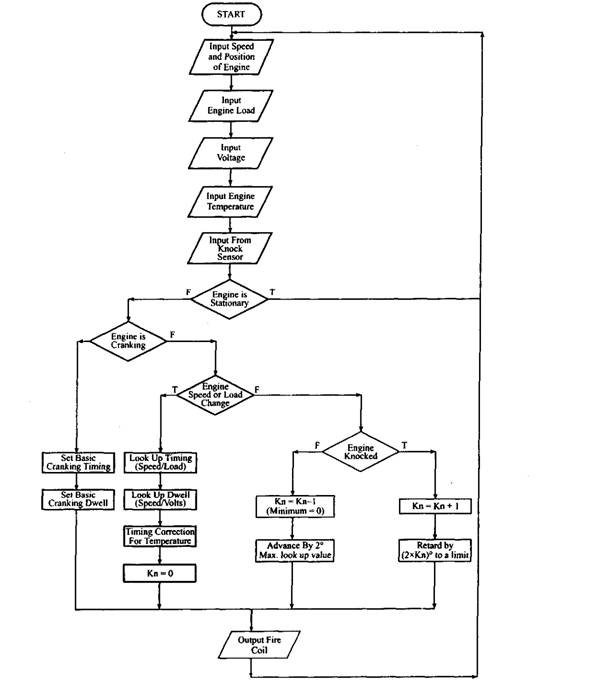
A separate three dimensional map, containing eight speed and eight temperature locations, is also used to incorporate corrections for engine coolant temperature to the basic timing settings. This improves driveability and can be used to decrease the warm-up time of the engine. The data also need an additional load correction below 343 K. Figure 16.54 represents a flow chart for logical selection of the optimum ignition settings. The ECU also incorporates corrections to the dwell angle, due to changes in battery voltage and also as a function of engine speed to provide constant energy output. A slightly longer dwell is required for a lower battery voltage and a slightly shorter dwell for higher voltage.
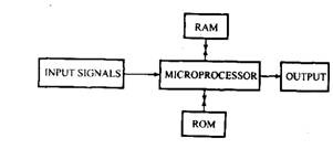
A block diagram of a typical programmed ignition ECU is shown in Fig. 16.55. Input signals are processed and the data provided is stored in RAM where as the program and preset data are held in ROM. A micro-controller is used to execute sequences demanded by the program. The sensors readings are converted to a digital representation in an analogue-to-digital circuit. Many manufacturers including Rover use an on-board pressure sensor to indicate engine load and is consisted of an aneroid chamber and strain gauges.

Fig. 16.54. Flow chart for the logical selection of optimum ignition timing.
Figure 16.54 shows a flow chart used to represent the program held in ROM. The programmed ignition system of Rover including the electronic control unit was quite advanced and shown high reliability compared to other contemporary systems.
16.4.4.
Ignition Output
The output from this programmed ignition is very simple and is in common with most electronic ignition. The output stage consists of a heavy duty transistor, which forms part of, or is driven by, a Darlington pair. This allows control of the high ignition primary current. The switch-off point of the coil controls ignition timing whereas the switch-on point controls the dwell period.
16.4.5.
High Tension Distribution
The high tension distribution is similar to a conventional system. The rotor arm, however, is installed at the end of the camshaft. The distributor cap is positioned over the top and is fixed on a base plate made of Crasline. This mounting point prevents any oil, which leaks from the camshaft seal, fouling the cap and rotor arm. The cap is made of Vela, which is similar to epoxy resin but has better electrical characteristics. The mounting plate also prevents the build-up of harmful gases such as ozone and nitric oxide by venting them to the atmosphere. These gases are generated by the electrolytic action of the spark as it jumps the air gap between the rotor arm and the cap segment. The rotor arm is also made of Crasline and is reinforced with a metal insert to relieve fixing stresses.

Fig. 16.55. Programmed ignition ECU block diagram.
