16.5.
Distributorless Ignition
16.5.1.
Principle of Operation
Distributorless ignition system used extensively by Ford incorporates all the features of electronic spark advance systems, except a special type of ignition coil is used in place of HT distributor. The system is generally used only on four- or six-cylinder engines, because the control system becomes highly complex for higher number of cylinders. It works on the principle of the lost spark. The spark distribution is achieved by the help of two double ended coils, fired alternately by the ECU. The ignition timing is obtained from a crankshaft speed and position sensor as well as through load and other corrections. When one of the coils is fired, a spark is delivered to two engine cylinders, either 1 and 4, or 2 and 3. The spark delivered to the cylinder on the compression stroke ignites the mixture as normal. Whereas the spark in other cylinder causes no effect, as this cylinder is just completing its exhaust stroke. Because of the low compression and the exhaust gases in the lost spark cylinder, the voltage only of about 3 kV is needed for the spark to jump the gap. This is similar to cap voltage of the more conventional rotor arm. The spark produced in the compression cylinder is therefore not affected.
It may be noted that the spark on one of the cylinders jumps from the earth electrode to the spark plug centre, whereas in others it jumps from the centre electrode. This is because the energy available from modern constant energy systems produces a spark of suitable quality in either direction. However, the disadvantage is that the spark plugs may wear more quickly with this system.
16.5.2.
System Components
The distributorless ignition system contains three main components such as the electronic module, a crankshaft position sensor and the distributorless ignition coil. Many sytems use a manifold absolute pressure sensor, integrated in the module. The module functions almost in the same way as the electronic spark advance system.
The crankshaft position sensor operates in the similar way to the one described in the previous section. It is also a reluctance sensor positioned against the front of the flywheel or against a reluctor wheel just behind the front crankshaft pulley. The tooth pattern uses 36-1 teeth, which are spaced at 10 degree intervals, with a gap for the 36th tooth. The missing tooth is located at 90 degrees before TDC for numbers 1 and 4 cylinders. This reference position is located a fixed number of degrees before TDC for calculating the timing or ignition point as a fixed angle after the reference mark.
The distributorless ignition coil (Fig. 16.56) has a low tension winding, which is supplied with battery voltage to a centre terminal. The appropriate half of the winding is then connected to earth in the module. The high tension windings are separate and are specific to cylinders 1 and 4, or 2 and 3. Figure 16.57 shows a typical Ford distributorless ignition coil. The Citroen 2 CV has been using a double ended ignition coil together with contact breakers for many years.

Fig. 16.56. Distributor-less ignition coil as part of the complete system.

Fig. 16.57. Distributorless ignition coils. A. 2-Spark coil. B. 2 x 2 Spark coil.
C. 3 x 2 spark coil (Bosch).
16.5.3.
Fault Diagnosis
The distributorless ignition system is highly reliable, specifically because it does not have any moving parts. The normal manufacturers servicing schedule should be adhered to for the replacement of spark plugs (often after 19,200 km operation). Some problems may be faced when trying to examine HT oscilloscope patterns, due to the lack of a king lead. This can be overcome by using a special adapter and shifting the sensing clip to each lead in turn.
An ohmmeter can be used to test the distributorless ignition coil. The resistance of each primary winding should be 0.5 Q and the secondary windings between 11 and 16 kQ. The coil produces open circuit voltage in excess of 37 kV. The plug leads have integral retaining clips to prevent water ingress and vibration problems. The maximum resistance for the HT leads is 30 kQ per lead. Except for the octane adjustment on some models no service adjustments are possible with this system. This adjustment involves connecting two pins together on the module
for normal operation, or earthing one pin or the other to change to a different fuel. The actual procedure as specified by the manufacturer for each particular model should be followed.

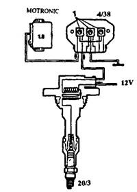
Fig. 16.58. Cross section of the direct ignition coil (Bosch) (1 refers to switching stage).
