27.2.
Front Wheels Alignment
27.2.1.
Need for Front Wheel Alignment
For free movement of the road-wheels with the least of effort, opposite wheels must be approximately parallel to each other when the vehicle is in motion along a straight path (Fig. 27.8). Each wheel has a tendency to negotiate a path perpendicular to its own axis of rotation. Therefore, if the front wheels are aligned for converging towards the front, then during movement in the forward direction both wheels try to roll close together. On the other hand, if the wheels are aligned for diverging towards the front, the wheels try to roll farther apart. Therefore due to free rolling tendency the average path followed by both wheels have a continuous tendency to either push together or pull apart. Consequently, while rolling forward, each wheel simultaneously tends to slip laterally, so a continuous cross tread scrub action is established, resulting in excessive tread wear, heavy steering and probably leading to poor fuel consumption.

Fig. 27.8. Effects of wheel misalignment. A. Forward direction, wheels converging. B. Forward direction, wheels diverging.
A tyre tread if subjected to excessive lateral slip or scrub, a diagonal wear pattern is observed, with the tread blocks heavily worn on the leading side and an extruded feather like appearance on the trailing side. Figure 27.8A illustrates the inward feathering of the tread blocks of converging wheels. If the hand is moved inward over the tread then smoothness is felt. Figure 27.8B illustrates the usual outward feathering of the tread blocks and grooves of diverging wheels. An inward movement of the hand over the tread feels a slight roughness. For a correctly aligned and parallel-rolling wheels, an even wear pattern across the tyre tread is produced so that inward and outward movements of the hand across the thread experience smoothness.
27.2.2.
Centre-point Steering
Figure 27.9 illustrates a vertical wheel and king pin arrangement, which has the following disadvantages:
(a) Large splaying-out effect of the wheel takes place.
The wheels are pushed by the force, F, which is opposed by the resistance, R. These two forces cause a couple, Fx, whose magnitude becomes very large when the front brakes are applied.
(6) Steering becomes heavy because of the distance between king pin and wheel centre. The wheel moves in an arc of radius, x, around the pin.
(c) Large bending stress occurs on the stub axle and king pin.
To overcome these problems, the wheel and king pin should have minimum possible offset distance, x. When the offset is eliminated, the centre line of the wheel meets the centre line of the king pin at the road surface. The condition is called centre point steering, which can be obtained through (a) camber (b) swivel-axis inclination or (c) dished wheels. Although the centre point steering appears to be ideal, but the spread effect of the pneumatic tyre causes the wheel to scrub and produce hard steering and tyre wear.
Camber.
The down-set of the stub axle tilts the wheel outwards at the top, forming an angle between the vertical and the wheel, which is termed the camber angle. The outward inclination is called positive camber and the inward inclination is the negative camber. The camber prevents the top of the wheels from tilting inward much due to excessive load or plays in the king-pin and wheel bearings. Camber on any automobile is the result of the front end geometry. Incorrect camber usually is noticed due to abnormal tyre wear along one half of the tread. Camber is adjustable by charging the position of one end of the steering knuckle.
Although the bending stress on the stub axle and the splaying out couple are reduced, but the different rolling radius of the tyre produce a cone effect, which gives rise to tyre wear and another splaying out action. Equal camber angles are provided to balance this action; otherwise the vehicle pulls to the side of greater camber. However unequal tyre pressures can also produce this effect.
Some independent suspension systems very the camber angle as the suspension spring deflects. This variation is from the positive camber shown in Fig. 27.10 to the negative camber, which is the inner tilt of the wheel. Suspension linkages alter the chamber angle when the suspension goes to jounce or rebound. Some suspensions have negative camber during both

” Fig. 27.9.
A vertical wheel and king pin arrangement having
disadvantages.
jounce and rebound so that the tyre tread centre line follows a straight path down the load. Other suspensions have positive camber during jounce and negative camber during rebound. This keeps the tyre tread surface flat on the road whejn going over bumps and dips. During a turn, high Negative camber on the outside tyre helps provide cornering power, as the tyre deflects under the high side loads due to centrifugal force on the automobile. This high negative camber also causes rapid tyre wear. The overall suspension camber is a compromise of these factors to provide the desired handling characteristics.
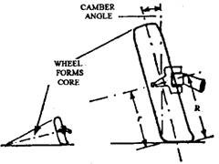
Fig. 27.10. Wheel camber (positive).
Since camber is not desirable from the consideration of a tyre wear, the angle seldom exceeds 2 degrees. This is sufficient to provide a slight outward-thrusting torque to allow road camber and slight deflections of the beam or suspension members. Excessive camber gives rise to improper contact of the wheels.
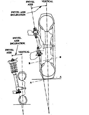
Fig. 27.11. Swivel axis inclination.
King Pin Inclination or Swivel-axis Inclination.
If the king pin is fitted outwards at the bottom, an angle between the king pin centre line and the vertical is produced (Fig. 27.11), which is known as king pin inclination (KPI) or swivel
axis inclination (SAI). Normally a king pin inclination of between 5 to 10 degrees is provided to obtain the required offset. The larger angles are necessary for a layout when the wheel is moved away from the king pin to accommodate brakes, bearings, etc.
When the wheel is turned, it moves in the plane AA such that the front of the vehicle is lifted, producing a self centring action. With vertical king pins, a simple yoke-and-pin type of steering joint can be incorporated at each end of the track rod. An inclined king pin allows the joint to move in the plane BB, upwards at one end of the track rod and downwards at the other. A ball joint is used to each end of the rod to permit this motion.
King-pin inclination is also called as steering axis inclination and king-pin or ball joint centre line is called steering axis centre line. The king-pin-centre line, if extended, contacts the road surface near the tyre tread centre line. The distance between the points of intersection of these two centre lines on the road surface is called scrub radius. A small scrub radius minimises steering wheel shock from road irregularities and reduce steering effort, and hence is desirable. The scrub radius is designed into the knuckle and spindle. If knuckle is damaged or bent, the scrub radius becomes incorrect. This damage of the knuckle can be detected by measuring both camber and steering axis inclination.
If the steering axis centreline contacts the road surface inside the tyre tread centreline, the scrub radius is positive. If it contacts the road surface outside the tyre centre line, the scrub radius is negative. The effect of unequal brake force on the front wheels increases when the scrub radius is large. This pulls the vehicles side-ways as the brakes are applied causing poor vehicle control. The wheel with high braking force pulls outward on a suspension with a positive scrub radius. Also a vehicle with positive scrub radius tends to pull outward or towards the side with an under inflated tyre.
Steering axis inclination positions the automobile body as low as possible when the wheels are in straight ahead position. As the wheels are turned in either direction, the tip of the spindle tries to move downward, but it cannot happen practically as the spindle is in the centre of the
wheel and the wheel is in contact with the ground. The spindle, therefore, pivots in the ball joint and tries to lift the vehicle. The weight of the automobile produces a strong tendency to turn the wheels to a straight ahead position after the turn has been completed. This force is sufficient to provide excellent directional stability so that the vehicle has a natural tendency to run straight ahead. The steering axis inclination angle is selected as a compromise between steering effort, neutral returning force and wheel pull sensitivity.
The inclination of the swivel axis or the tilting of the king pin can be obtained with the help of one of the following methods.
(i) Upper independent suspension members are mounted slightly to the rear of the lower members.
(ii) The axle beam of a light truck is tilted by
(a) fitting wedges between axle and spring,
(b) mounting the axle towards the front of a laminated spring, and
(c) inclining the laminated spring.
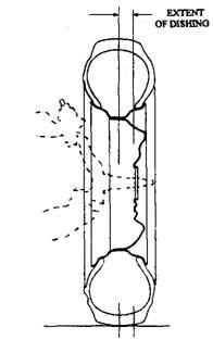
Fig. 27.12. Dished wheel.
By slightly dishing the wheel (Fig. 27.12), the amount of camber and king pin inclination can be reduced. The light pressed-steel wheel must not be excessively dished, as it decreases the strength.
Negative Offset (Negative Scrub Radius).
In the earlier days positive offset was used which is obtained when the centre line of the wheel meets the swivel axis at a point just below the road. The offset distance, measured at the road surface between the two centre lines, should be equal to balance the inward or outward pull at both the wheels. If one front tyre deflates, the positive offset on that side increases. This causes the vehicle to pull severely to that side so that is becomes difficult for the driver to maintain control especially during application of the brake (Fig. 27.13). Consequently, to improve road safety negative offset is provided by the manufacturer. In this case the swivel axis is inclined more than the earlier in order to obtain an interaction point well above the road surface. With this layout the effect of tyre deflection shortens the offset. The rolling resistance, however, increases, but the shorter offset robs the deflated tyre of leverage to change the direction of the vehicle.
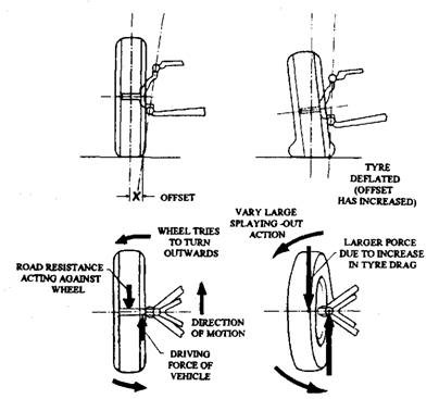
Fig. 27.13. Positive offset.
The negative offset also provides an additional safety when the front brakes are unbalanced due to poor adhesion of one wheel or failure of one front brake. Under these adverse conditions the vehicle can still be brought to rest in a straight line. Figure 27.14 illustrates when the right hand front brake fails, the geometry causes the braking action of the left hand wheel to steer the wheels to the right to compensate the loss of brake drag on the right hand side of the vehicle. Also the negative offset layout is specifically suitable for a diagonally connected split line braking system.
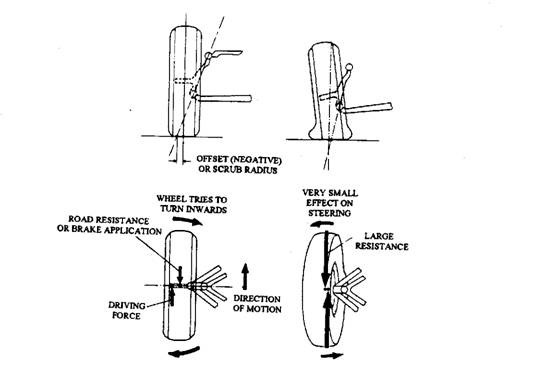
Fig. 27.14. Negative offset.
27.2.3.
Castor
Caster angle is the tilt of the king pin or ball joint centre line from the vertical towards either the front (negative caster) or rear (positive caster) of the vehicle (Fig. 27.15). The weight of automobile having positive castor tends to turn a wheel inward to allow the body to lower. Negative castor causes an outward turning effect. Wheel castor enables the driver to feel the straight ahead position so that he may steer in a straight path. During cornering, a torque must be exerted on the steering wheel to overcome the self centring or castor action, which tends to keep the wheels pointing straight ahead. The castor angle produces a trailing effect and hence gives the directional stability. Incorrect castor can produce difficulties like hand steering, pulling to one side when brakes are applied and shimmy. To understand the action of this steering feature, the operation of a simple furniture castor (Fig. 27.15A) fitted to a trolley may be considered. Force acting on the trolley causes it to move in the direction of the force. The figure illustrates the effect of this force on the castor. The force, F, acting at the pivot and the resistance acting at the wheel produce a couple, which rotates the castor to a position where the wheel is following the line of thrust.
On a motor vehicle the pivot centre line normally strikes the road in front of the centre of contact of the wheel, so that the wheel follows the path taken by the pivot centre line, which is always in front of the wheel. Castor can be obtained by mounting a vertical king pin infront of the wheel (Fig. 27.15B) or by inclining the king pin forward at the bottom (Fig. 27.15C). The latter arrangement is simpler, and hence used by most manufactures. The caster angle of between 2 to 5 degrees is generally provided and the tolerance is normally +0.5 degree for all steering angles.
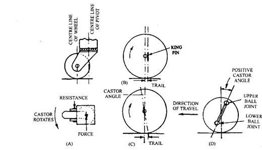
Fig. 27.15. Wheel castor.
In Fig. 27. 15D the pivot centre line makes contact with the road in front of the centre line of the wheel, providing positive castor. This layout is normally used for a rear wheel drive arrangement but is unsuitable for front and four-wheel drive vehicles. This is because the conditions shown in Fig. 27.15D are then reversed. Vehicles using the front wheels drive generally have negative castor (Fig. 27.15C), however, the manufacturer’s data should be referred while checking the steering geometry. Castor adjustments can be made on most cars by repositioning the inner pivots of the upper control arm to move the upper ball joint forward and backward.
27.2.4.
Front-wheel Toe-in or Toe-out
Toe-in is the amount by which the front-wheel rims are set closer together at the front than at the rear with the wheels in straight ahead position when the vehicle is stationery (Fig. 26.16A). Alternatively, toe-out is the amount by which the front-wheels rims are set farther apart at the front than at the rear (Fig. 27.16B). Therefore in Fig. 27.16, toe-in =Tr-Tf and toe-out = Tf-Tr.

Fig. 27.16. Steering toe-in and toe-out.
Toe-in or toe-out compensates for movement within steering ball-joints, suspension rubber bush-joints, and any slight deflection of the track-rod arms or suspension arms when the vehicle is in motion. The objective of the non-parallel stationary alignment of the front steered wheels is for the toe-in or toe-out to be taken up when the vehicle is moving, so that both wheels run parallel under normal driving conditions.
Toe-in neutralises the cone rolling effect of front wheels caused by camber angle. The amount of toe-in for any vehicle, therefore, is primarily determined by the amount of camber angle. Toe-in is usually 2 to 4 mm. Toe-in turns to zero as the dynamic forces develop to deflect steering linkages and take-up slight clearances. Excessive steering linkage looseness, however, allows the wheels to toe-out under dynamic loads. Toe-in and toe-out causes excessive tyre wear. Toe is adjusted with threaded sleeves on linkage members called tie-rods. Booth sides must be adjusted to hold the steering wheel centred as the vehicle goes straight.
A rear-wheel-drive steering and suspension layout is shown in Fig. 27.17. While driving, the propelling thrust pushes the suspension cross member and body forwards, which is resisted by the road reaction on the tyres. This produces outward twisting of both the wheels so that the suspension wishbone rubber bushing distorts causing the front wheels to diverge. To counteract this tendency the wheels are initially provided with a toe-in so that under driving conditions the wheels run parallel.
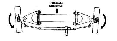
Fig. 27.17. Rear-wheel drive steered wheel reaction due to forward motion.
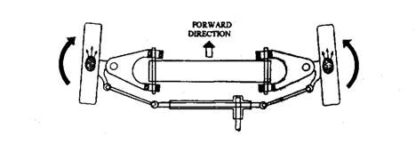
Fig. 27.18. Front-wheel drive steered-wheel reaction due to forward motion.
A front wheel drive steering and suspension layout is shown in Fig. 27.18. In this case the driving traction is imparted to the front wheels due to which the stub axle assembly is pulled forward the suspension cross member and body. The wheels twist inwards due to the natural reaction and so distort the suspension wishbone rubber pivot joints in a horizontal plane causing the front wheels to converge. To counteract this converging tendency under driving conditions, the wheel track is provided with a toe-out, which is equal to the amount of distortion in the horizontal plane expected when the vehicle is being driven. This is an oversimplified presentation. Considering other variations and combinations in steering and suspension geometry, front wheel drive vehicles sometimes have zero toe-out.
Toe-out-on-turns.
When a vehicle takes a turn, the inside wheel moves faster than the outer wheel because the former has to negotiate an arc with shorter radius than the latter. This action causes the wheels to toe-out-on-turns because of difference in their turning angles. This relates to the diverging of the front wheels in the forward direction when the stub-axles are rotated about their king-pins (Fig. 27.19). The difference between the angles of turn of the front steered wheels provides the value of the toe-out in degrees. The amount of toe-out on turns depends upon the track rod arm length, its angular set and the track width, and is obtained by the inclination or set of the track rod arms.
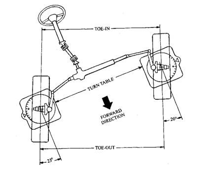
Fig. 27.19. Toe-out angle on turns.
To measure the toe out angle on turns, the front wheels are rolled on to radius or turntable gauges in the straight ahead position and then the pointer of each gauge is set to zero. The outer road-wheel is then turned through 20 degrees as indicated on the turntable scale, and the opposite inner wheel angle is observed on its scale, which generally should read between 20.5 degrees and 23 degrees. The toe-out angles on each lock should be approximately equal and it is more important than the actual amount. A vehicle having excessive tyre wear but with a correctly aligned track in the straight ahead position should be checked for the angular toe-out of the inner wheel with the outer wheel set at 20 degrees. Any error between the readings on both sides may be due to a bent track rod or arm, etc.
27.2.5.
Wheel Alignment Checking and Adjustment
The alignment for suspension and steering linkage is usually checked and adjusted if, GO abnormal tyre were exists,
(ii) the automobile handling is felt improper,
(Hi) the suspension has been repaired, or
(iv) a normal preventive maintenance check becomes necessary.
In the past the wheel alignment was measured using a trammel gauge, but nowadays either an optical or an electronic gauge is used. Before tracking the wheels, the following preliminaries should be undertaken.
(a) The tyre pressures are checked.
(b) The correct load on the vehicle is ensured.
(c) The wheels are positioned in the straight ahead position.
(d) The vehicle is moved forward to settle the steering.
(e) The run-out (buckle) of the wheel in checked and the maximum run-out is positioned so that it does not affect the alignment measurement.
Prior to aligning the front suspension and steering systems, the factors to be ascertained that the suspension pivots and ball joints are in good condition, the spring height is correct, the shock absorbers are in good condition, and the tyres are inflated to the correct pressure. Tyres should be inspected for any specific problems. Tyre wear on one side of the tread generally is due to improper camber on the wheel. Smooth tyre wear on both sides of both front tyres indicates excessive slippage when negotiatimg corners at high speeds. Wear on the edges of one tyre normally is due to under-inflation of that tyre and wear on centre portion of the tyre tread is due to over-inflection.
The status of wheel alignment can also be ascertained by observing the wafer edge of rubber left on the side of the tread pattern (Fig. 27.20). The position of the feather is examined to provide an indication of the fault. Feather edge indicates improper toe and copping around the tyre edge, which may be caused by under-inflation or by suspension mechanical irregularities. A wafer of rubber on the inside of the tread recognises that the wheels are toe-in and vice versa. This type of feathering of the tread is often more prominent on one tyre than the other.
Both portable and stationary alignment machines are available. Alignment racks or wheels stands are either above the floor or extended over a pit in which the mechanic can Work comfortably. The alignment rack must be level to compare the alignment angles with the vertical lines. Turntables are located under the front tyres so that the wheels can be turned left or right. Alignment gauges to sense a vertical position are usually a bubble level or a swing weight. Instrument heads are mounted to the front wheels or to the spindle through adapters. Both the front wheels turn towards the near-side due to the combination of road camber and the action of the tyre’s self-righting torque. This movement affects the steering geometry and justifies “‘hy
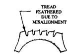
Fig. 27.20. Section through tyre treads.
a manufacturer recommends a toe setting which appears to contradict basic theory. Due to interaction between the various geometries of a modern vehicle it becomes difficult to pinpoint the cause of a fault from a given symptom. Therefore, a front-end check covering all aspects of geometry is recommended after completing the preliminaries.
Once the instrument head is levelled the camber is read directly from the instrument head or screen. Castor is measured as it affects camber during a turn. Castor is read on a special scale which converts the camber change into a castor. When the wheel is turned from 20 degrees inward to 20 degrees outward with the brake applied, the change in camber indicates castor. If castor is zero, no change in camber is observed as the wheels are turned. Camber change increases with increase of castor as the wheel turns 40 degrees. Steering axis inclination is also measured in a manner similar to castor. But, this measurement includes a change in castor during the 40 degrees wheel turn instead of camber change. Therefore a different scale is necessary for converting this reading. Some vehicles fitted with independent rear suspension incorporates an adjuster for rear wheel alignment.
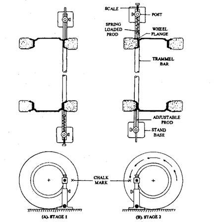
Fig. 27.21. Trammel wheel track alignment gauge.
Alignment readings are compared to the manufacturer’s specifications and appropriate action is taken in case of the difference in readings. The majority of domestic vehicles incorporate a means to adjust both upper control arm pivot points through shims, cams, or slots. Both castor and camber can be adjusted at only one of the pivot points. Some vehicles use an eccentric
adjustment system around the upper ball joint to adjust camber and other use a cam at the lower control arm pivot. In both methods the camber is controlled by changing the relative position of the steering knuckle, spindle, wheel, and tyre. In some vehicle models castor is adjusted increasing or decreasing the length of the lower control arm strut. The front strut-to-frame attachment has adjustment nuts that move the lower end of the knuckle forward or backward to change caster.
Steering axis inclination cannot be adjusted independent of camber, but is used only to check for a bent steering knuckle. When both camber and steering axis inclination deviate from their respective specification range, the knuckle is bent. After the wheel alignment adjustments a road test should always be conducted to ensure that the car tracks straight and is handled properly.
Adjustment of the front wheel parallelism for true rolling also sets the static toe-in or toe-out recommended by the vehicle manufacturer. The adjustment is carried at by increasing or decreasing the length of the track-rod or tie-rods until the correct track-alignment setting is obtained. For correction of the alignment, left and right handed screw threads are provided on the track rod to alter the length of the rod. If the layout has a rack-and-pinion steering box, equal adjustment of the two outer rods is necessary, otherwise the position of the steering wheel alters and the steering locks become unequal.
The trammel gauge, the simplest track-alignment tool, is a horizontal bar that can slide in slots formed in a pair of perpendicular posts that stand on the floor. One post has an adjustable fixed prod and the other post has a spring-loaded prod with a reference scale (Fig. 27.21). To obtain a correct reading, the track alignment should be checked on level ground. The following procedure may be followed for checking the track alignment with the trammel gauge.
(i) The trammel bar is placed across and in front of the steered wheels, with the posts positioned on the outside of each wheel and the prods pointing towards the wheel rims. The fixed prod is set against the wheel inner rim.
(ii) The spring-loaded prod is pulled and released, which presses against the other wheel inner rim and then the scale reading is observed.
(Hi) The points where each prod touches the rim is marked with chalk and then the vehicle
is rolled forward till the wheels turn through exactly 180 degrees, so that the chalk
marks are now at the rear of the wheels. (iv) Now the trammel bar is positioned behind the steered wheels, with the fixed prod just
touching inner rim and the spring-loaded prod free to adjust itself to the inner rim.
The difference in reading between the front and rear measurements gives the toe-in
or toe-out.
