3.10.
Camshaft
The camshaft performs as a means of actuating the opening and controlling the period before
closing both the inlet and the exhaust valves. Also, it provides a drive for both the ignition
distributor and mechanical fuel pump. The camshaft ensures occurrence of the cycle of events

Fig. 3.71. Camshafts chain driven by the crankshaft.

Fig. 3.72. Cylinder-block-mounted camshaft. Fig. 3.73. Cylinder-head-mounted camshaft.
at the correct time in relation to the movement of the pistons. It also ensures, simultaneously,
the sequential operations of each valve in accordance to the firing-order.
The camshaft (Fig. 3.71) is the second rotating shaft placed in the crankcase, and installed
to one side and above the crankshaft. It is generally supported by three or four sleeve bearings
and fitted with two cams for each cylinder to operate the valve lifters for opening and closing
the valves in proper order and at the correct time. Towards the centre of the camshaft a gear is
mounted to drive the oil pump shaft and the distributor shaft at the same speed as the camshaft.
The camshafts are installed in the cylinder block
parallel to the crankshaft and to one side of the
cylinder either just above the crankshaft (Figs. 3.1
and 3.2) or a little below the cylinder head (Fig. 3.71).
Alternatively, the camshaft can be mounted centrally
over the cylinder head on a pedestal support (Figs.
3.72 and 3.73). Usually three plain bush-type white-
metal or tin-aluminium bearings support the cam-
shaft. These bearings are a force fit in the cylinder
block or head-pedestal housing bores.
3.10.1.
Crankshaft-to-camshaft Drive
The crankshaft drives the camshaft through a
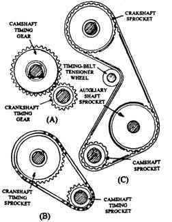
pair of mating gears, called timing gears (Fig. 3.74 A),
each installed at one of their ends. The camshaft gear
carries exactly double number of teeth to that of
crankshaft gear. This enables the camshaft to rotate
at half the speed of the crankshaft so that each valve
opens only once in every two revolutions of crankshaft
in case of four-stroke engine. This directly geared
simple train is suitable only for low-mounted cam-
shaft in the cylinder-block. Therefore this timing- A Gear drive (for low-mounted camshaft).
gear arrangement is used with push-rod-actuated B Chain drive Qror high-mounted cam
‘V-six’ and ‘V-eight’ engines. shaft).
For the engine with a high-mounted camshaft in & Belt drive (for overhead camshaft)
the cylinder block, an additional idler gear is necessary between the crankshaft and camshaft
gears or alternatively a timing gear chain (Figs. 3.74B and 3.71) can be used to span the distance
between the driver and driven gear wheels. With correct tensioning and proper lubrication,
these chains can have a service life of at least 140 000 km.
Internally toothed belts (Fig. 3.74C) are commonly used for both petrol engines and small
diesel engines fitted with an overhead camshaft. These belt-drives run relatively silently,
operate dry against the sprocket wheels and have a life span of about 50000 to 70000 km under
normal driving conditions. For speed reduction, the camshaft driven gear or sprocket-wheel has
twice as many teeth on the driver camshaft wheel. The belt also transmits power to an auxiliary
shaft used to drive the distributor or the injection pump.
The camshaft rotation is correctly timed to the rotation of crankshaft through timing gears
so that the valves are opened and closed in relation to crankshaft angle and piston position.
Cam lobe shape or contour has more control over engine performance characteristics than any

Fig. 3.74. Camshaft drive arrangement.
other single engine part. A spherical lifter face of 1700 mm to 1432 mm diameter is used in most
of the valve trains, which slides against the cam lobe. It contacts the lobe off-centre as the lobe
has a slight taper across its face. This produces a turning effort on the lifter which causes
rotation. The cam lobe has a wide line contact with the lifter where the highest pressure zone
exists on the surface. As the camshaft lobe pushes the lifter upward against the valve spring
force, backward torsion force is developed in the camshaft. After the lobe goes past its highest
point, the lifter moves down the back side of the lobe, causing forward torsion force. These
alternating torsion forces are multiplied by the number of cam lobes on the camshaft. This
requires the camshaft to be sufficiently strong to withstand torsion and be tough enough to
minimize fatigue.
3.10.2.
Camshaft Materials
At present chilled cast iron is almost universally used for the manufacturing of the
camshafts. The metal chills (shaped pieces of cast iron) are placed in the walls of the mould
adjacent to where the cam lobes are to be located, so that when the molten iron is poured it
freezes rapidly in these selected zones. The chilled zone is a complex composite casting a section
of which normally exhibits three distinct zones ;
(a) an outer layer of the white-iron, containing a fine mixture of hard carbides and soft
pearlite,
(b) a tarnsition zone with a mottled appearance, which consists of both a carbide-pearlite
mixture and graphitic grey iron together,
(c) a core region predominating the normal soft and ductile graphitic grey-iron structure.
The composition of a typical cast-iron alloy used for camshafts is 3.30% carbon, 20% silicon,
0.65% manganese, 0.65% chromium, 0.25% molybdenum, and 93.15% iron. The camshaft is cast
as one piece with lobes, bearing journals, drive flanges and accessory gear blanks closed to the
finished side. Cam lobe contour requires very careful machining as they are most critical.
Steel camshafts have been used in some heavy duty engine camshafts and are necessary in
engines using roller lifters. The camshaft gear teeth are made of soft material to reduce noise.
The camshaft gear or sprocket is made of sintered iron or it may have an aluminium hub with
nylon teeth. The timing chain is either a silent chain or roller chain.
