3.8.
Flywheel
The functions of a flywheel are the following :
(a) It stores up energy to help the engine over idle
strokes of the piston i.e., suction, compression
and exhaust.
(b) It dampens out speed fluctuations of the
crankshaft due to the varying effect of the firing
impulses during the engine cycle.

Fig. 3.66. Flywheel and ring gear.
(c) It provides a convenient mounting
point for the clutch and starter ring
gear.
The flywheel (Fig. 3.66) is a heavy and
perfectly balanced wheel usually bolted to a
flange on the rear end of the crankshaft. En-
gines with many cylinders do not require as
heavy a flywheel as an engine with fewer
cylinders because of power lap.
3.8.1.
Flywheel Attachment
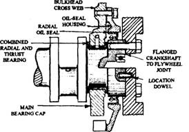
The flywheel end of the crankshaft uses a
larger diameter (Fig. 3.62) than the main jour-
nals, which provides a flanged face to mount the
flywheel and to support a circumferential rub-
bing surface for the rear crankshaft oil-seal. A
shallow recess in the flywheel allows it to be
aligned over the flanged end of the crankshaft,
which provides concentric (radial) support for
the joints (Figs. 3.67 and 3.68). In order to
prevent relative angular movement between
the crankshaft and the flywheel, dowels are
countersunk at one or two locations in both
mating faces. Alternatively, one of the clamping
bolts is used with a shoulder, which fits tight in its selected flywheel hole.
To transmit the drive torque from the crankshaft to the flywheel four or six bolts clamp
together the flanges and recessed faces of the two components. When installing the flywheel,

Fig. 3.67. Crankshaft-to-flywheel flanged joint and
oil-seal.
all the set-bolts should be initially lightly and
evenly tightened, followed by tightening
diametrically opposite set-bolts to the recom-
mended torque. If this tightening procedure is
not followed, excessive flywheel wobble, known
as run-out may occur.

Fig. 3.68. Main bearing with integral thrust
flange, oil-seal, and flywheel joint.
