The Offset tool
Examples – Offset (Fig. 5.14)
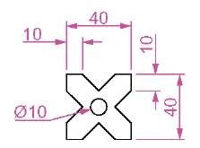
1. Construct the four outlines shown in Fig. 5.13.
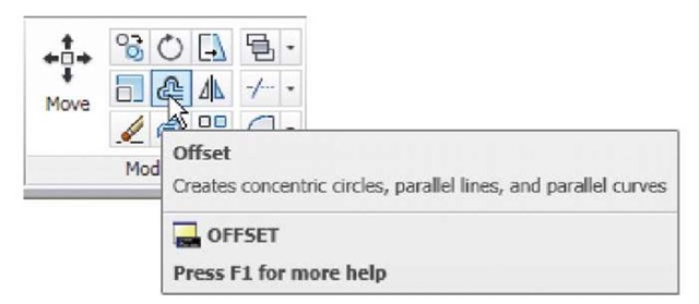
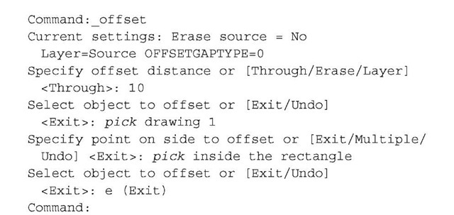
2. Call the Offset tool – left-click on its tool icon in the Home/Modify panel (Fig. 5.12), pick the tool name in the Modify drop-down menu or enter o or offset at the command line. The command line shows (Fig. 5.13):
Fig. 5.12 The Offset tool from the Home/Modify panel
Fig. 5.13 Examples – Offset – outlines
3. Repeat for drawings 2, 3 and 4 in Fig. 5.12 as shown in Fig. 5.14.
Arrays can be in either a Rectangular form or a Polar form as shown in the examples below.
Fig. 5.14 Examples – Offset
The Array tool
Fig. 5.15 First example – Array -drawing to be arrayed
First example - Rectangular Array (Fig. 5.17)
1. Construct the drawing Fig. 5.15.
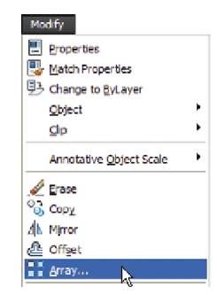
2. Call the Array tool - either click Array in the Modify drop-down menu (Fig. 5.16), from the Home/Modify panel, or enter ar or array at the command line. The Array dialog appears (Fig. 5.17).
3. Make settings in the dialog:
Rectangular Array radio button set on (dot in button) Row field – enter 5 Column field – enter 6
Row offset field – enter – 50 (note the minus sign) Column offset field – enter 50
Fig. 5.16 Selecting Array from the Modify drop-down menu
Fig. 5.17 First example – the Array dialog
4. Click the Select objects button and the dialog disappears. Window the drawing. A second dialog appears which includes a Preview< button.
5. Click the Preview< button. The dialog disappears and the following prompt appears at the command line:
6. If satisfied right-click. If not, press the Esc key and make revisions to the Array dialog fields as necessary.
The resulting array is shown in Fig. 5.18.
Second example – Polar Array (Fig. 5.22)
1. Construct the drawing Fig. 5.19.
2. Call Array. The Array dialog appears. Make settings as shown in Fig. 5.20.
3. Click the Select objects button of the dialog and window the drawing. The dialog returns to screen. Click the Pick Center point button (Fig. 5.21) and when the dialog disappears, pick a centre point for the array.
Fig. 5.18 First example – Array
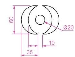
Fig. 5.19 Second example – the drawing to be arrayed
Fig. 5.20 Second example – Array – settings in the dialog
Fig. 5.21 Second example – Array – the Pick Center point button
4. The dialog reappears. Click its Preview< button. The array appears and the command line shows:
5. If satisfied right-click. If not, press the Esc key and make revisions to the Array dialog fields as necessary.
The resulting array is shown in Fig. 5.22.
Fig. 5.22 Second example – Array
