Aim of This Topic
The aim of this topic is to give examples of 3D solid models constructed in multiple viewport settings.
The 3D Modeling workspace
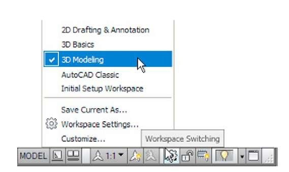
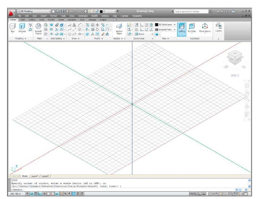
In topic 12 all 3D model actions were constructed in the 3D Basics workspace. As shown in that topic, a large number of different types of 3D models can be constructed in that workspace. In the following topics 3D models will be constructed in the 3D Modeling workspace, brought to screen with a click on 3D Modeling icon the Workspace Settings menu (Fig. 13.1). The AutoCAD window assumes the selected workspace settings (Fig. 13.2).
Fig. 13.1 Opening the 3D Modeling workspace
Fig. 13.2 The 3D Modeling workspace in SW Isometric view and Grid on
If the 3D Modeling workspace is compared with the 3D Basics workspace (Fig. 12.2) it will be seen that there are several new tabs which when clicked bring changes in the ribbon with different sets of panels. In Fig. 13.2 the menu bar is included. This need not be included if the operator does not need the drop-down menus available from the menu bar.
Setting up viewport systems
One of the better methods of constructing 3D models is in different multiple viewports. This allows what is being constructed to be seen from a variety of viewing positions. To set up multiple viewports.
Fig. 13.3 Selecting Four: Equal from the View/Viewports popup list
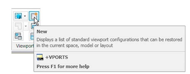
In the 3D Modeling workspace click New in the View/Viewports panel. From the popup list which appears (Fig. 13.3) select Four: Equal. The Four: Equal viewports layout appears (Fig. 13.4).
Fig. 13.4 The Four: Equal viewports layout
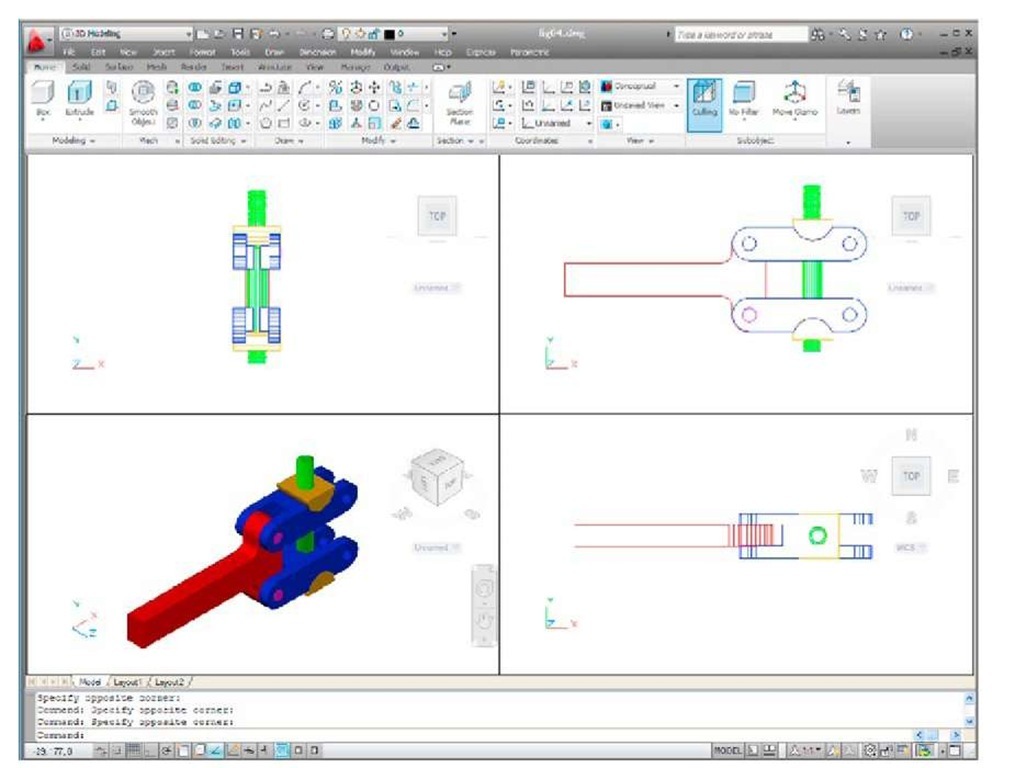
In Fig. 13.4 a simple 3D model has been constructed in the Four: Equal viewport layout. It will be seen that each viewport has a different view of the 3D model. Top right is an isometric view. Bottom right is a view from the right of the model. Bottom left is a view from the left of the model.
Top left is a view from the top of the model. Note that the front view viewport is surrounded by a thicker line than the other three, which means it is the current viewport. Any one of the four viewports can be made current with a left-click within its boundary. Note also that three of the views are in third angle projection.
When a viewport system has been opened it will usually be necessary to make each viewport current in turn and Zoom and Pan to ensure that views fit well within their boundaries.
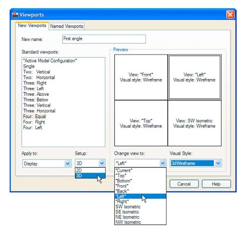
If a first angle layout is needed it will be necessary to open the Viewports dialog (Fig. 13.5) with a click on the New icon in the View/Viewports panel (Fig. 13.6). First select Four: Equal from the Standard viewports list; select 3D from the Setup popup menu; click in the top right viewport and select Left in the Change View popup list; enter first angle in the New name field. Change the other viewports as shown. Save the settings with a click on the Named Viewports tab and enter the required name for the setup in the sub-dialog which appears.
Fig. 13.5 The Viewports dialog set for a 3D first angle Four: Equal setting
Fig. 13.6 Selecting New from the View/Viewports panel
First example – Four: Equal viewports (Fig. 13.9)
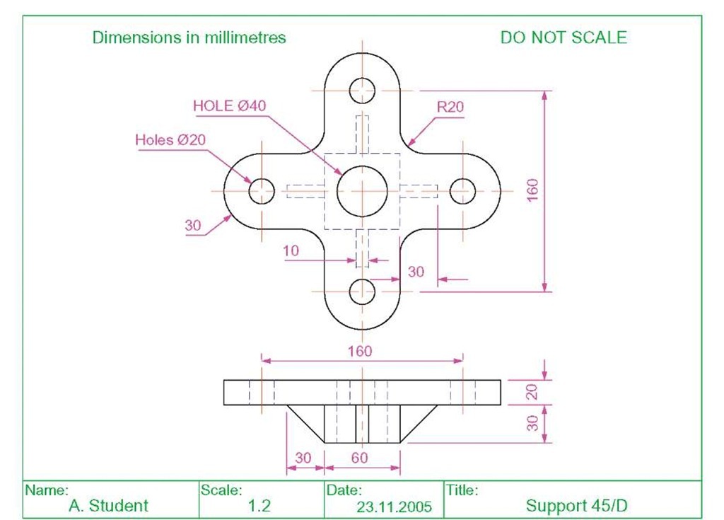
Fig. 13.7 shows a two-view orthographic projection of a support. To construct a Scale 1:1 third angle 3D model of the support in a Four Equal viewport setting on a layer colour Blue:
1. Open a Four Equal viewport setting from the New popup list in the View/Viewports panel (Fig. 13.3).
2. Click in each viewport in turn, making the selected viewport active, and Zoom to 1.
Fig. 13.7 First example – orthographic projection of the support
3. Using the Polyline tool, construct the outline of the plan view of the plate of the support, including the holes in the Top viewport (Fig. 13.5). Note the views in the other viewports.
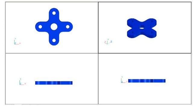
4. Call the Extrude tool from the Home/Modeling panel and extrude the plan outline and the circles to a height of 20.
5. With Subtract from the Home/Solid Editing panel, subtract the holes from the plate (Fig. 13.8).
Fig. 13.8 First example – the four viewports after Extrude and Subtract
6. Call the Box tool and in the centre of the plate construct a box of Width=60, Length=60 and Height=30.
7. Call the Cylinder tool and in the centre of the box construct a cylinder of Radius=20 and of Height=30.
8. Call Subtract and subtract the cylinder from the box.
9. Click in the Right viewport, with the Move tool, move the box and its hole into the correct position with regard to the plate.
10. With Union, form a union of the plate and box.
11. Click in the Front viewport and construct a triangle of one of the webs attached between the plate and the box. With Extrude, extrude the triangle to a height of 10. With the Mirror tool, mirror the web to the other side of the box.
12. Click in the Right viewport and with the Move tool, move the two webs into their correct position between the box and plate. Then, with Union, form a union between the webs and the 3D model.
13. In the Right viewport, construct the other two webs and in the Front viewport, move, mirror and union the webs as in steps 11 and 12.
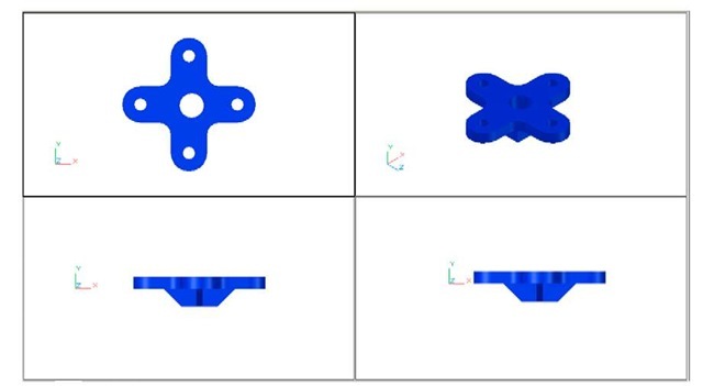
Fig. 13.9 shows the resulting four-viewport scene.
Fig. 13.9 First example – Four: Equal viewports
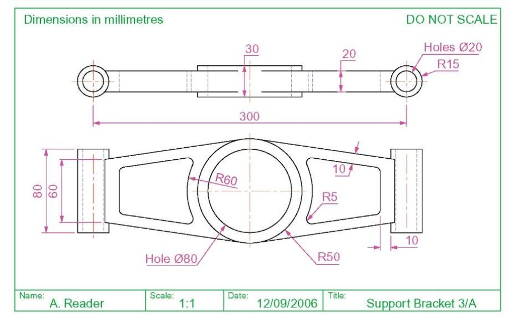
Second example – Four: Left viewports (Fig. 13.11)
1. Open a Four: Left viewport layout from the Views/Viewports popup list (Fig. 13.3).
2. Make a new layer of colour Magenta and make that layer current.
3. In the Top viewport construct an outline of the web of the Support Bracket shown in Fig. 13.10. With the Extrude tool, extrude the parts of the web to a height of 20.
4. With the Subtract tool, subtract the holes from the web.
Fig. 13.10 Working drawing for the second example
5. In the Top viewport, construct two cylinders central to the extrusion, one of radius 50 and height 30, the second of radius 40 and height 30. With the Subtract tool, subtract the smaller cylinder from the larger.
6. Click in the Front viewport and move the cylinders vertically by 5 units. With Union form a union between the cylinders and the web.
7. Still in the Front viewport and at one end of the union, construct two cylinders, the first of radius 10 and height 80, the second of radius 15 and height 80. Subtract the smaller from the larger.
8. With the Mirror tool, mirror the cylinders to the other end of the union.
9. Make the Top viewport current and with the Move tool, move the cylinders to their correct position at the ends of the union. Form a union between all parts on screen.
10. Make the Isometric viewport current. From the View/Visual Styles panel select Conceptual.
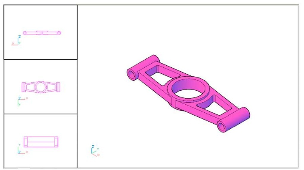
Fig. 13.11 shows the result.
Fig. 13.11 Second example – Four: Left viewports
Third example – Three: Right viewports (Fig. 13.13)
1. Open the Three: Right viewport layout from the View/Viewports popup list (Fig. 13.3).
2. Make a new layer of colour Green and make that layer current.
3. In the Front viewport (top left-hand), construct a pline outline to the dimensions in Fig. 13.12.
4. Call the Revolve tool from the Home/Modeling panel and revolve the outline through 360 degree.
5. From the View/Visual Styles panel select Conceptual.
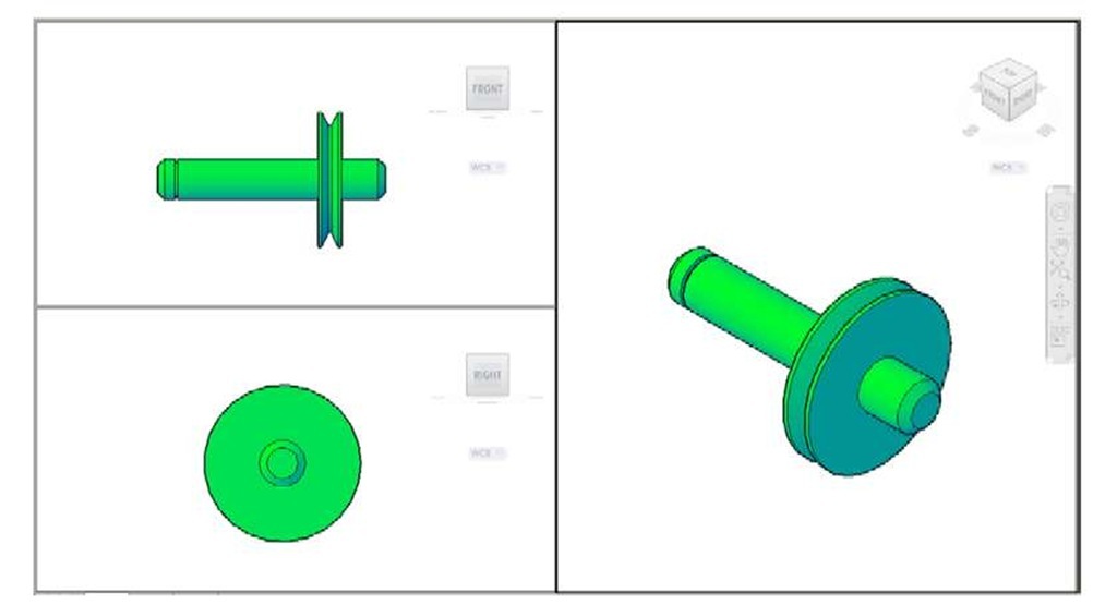
The result is shown in Fig. 13.13.
Fig. 13.12 Third example – outline for solid of revolution
Fig. 13.13 Third example – Three: Right viewports
Notes
1. When working in viewport layouts, make good use of the Zoom tool, because the viewports are smaller than a single viewport in AutoCAD 2011.
2. As in all other forms of constructing drawings in AutoCAD 2011 frequent toggling of SNAP, ORTHO and GRID will allow speedier and more accurate working.
Revision Notes
1. Outlines suitable for use when constructing 3D models can be constructed using the 2D tools such as Line, Arc, Circle and polyline. Such outlines must either be changed to closed polylines or to regions before being incorporated in 3D models.
2. The use of multiple viewports can be of value when constructing 3D models in that various views of the model appear enabling the operator to check the accuracy of the 3D appearance throughout the construction period.
