Universal Transverse Mercator Mapping
The geographical coordinates![]() locate a point on the reference ellipsoid. For many practical purposes it is useful to have a coordinate representation in the two-dimensional plane. The mapping of an ellipsoid into a plane may be done by a conformal mapping. Conformity leaves the shape of small figures while distances must be scaled.
locate a point on the reference ellipsoid. For many practical purposes it is useful to have a coordinate representation in the two-dimensional plane. The mapping of an ellipsoid into a plane may be done by a conformal mapping. Conformity leaves the shape of small figures while distances must be scaled.
The most widely spread conformal mapping was introduced by the Department of Defense in United States shortly after the Second World War. It is called the Universal Transverse Mercator Grid System (UTM). The reference ellipsoid is the International Ellipsoid of 1924. The mapping is defined for the whole Earth. It was a desire to limit the variation of the scale m so the total mapping of the Earth is divided into 60 sections that are named zones. Each zone covers 6° in longitude, and they are numbered from 1 to 60. Number 1 covers 180°-174° West, number 2 covers 174°-168° West, and so on. The scale at the central meridian is m0 = 0.9996. The UTM system is limited by the parallels 84° North and 80° South. The polar regions are mapped stereographically.
The coordinates are called northing N and easting E. Each zone has its own coordinate system. The central meridian has a false easting (FE) of 500,000 m and the equator has a false northing (FN) of 0 m for points on the northern hemisphere and a false northing of 10,000,000 m for points on the southern hemisphere. This simple arrangement leaves all coordinates positive.
The transformation of geographical coordinates![]() into UTM coordinates (N, E) and reversely appears often in practice. We point to the M-files geo2utm and utm2geo:
into UTM coordinates (N, E) and reversely appears often in practice. We point to the M-files geo2utm and utm2geo:
Dilution of Precision
The covariance matrix![]() as described in (8.25) contains information about the geometric quality of the position determination. It is smaller (and
as described in (8.25) contains information about the geometric quality of the position determination. It is smaller (and![]() is more accurate) when the satellites are well spaced.
is more accurate) when the satellites are well spaced.
The covariance matrix![]() is a 3 by 3 matrix in case we estimate (X, Y, Z) and a 4 by 4 matrix in case we estimate (X, Y, Z, c dt). It is positive definite, so its inverse exists and is likewise positive definite. We introduce a local coordinate system with origin at (XX, Y, Z) and with axes parallel to the original ones. In the local system, let the point x = (x, y, z)T lie on a surface described by the quadratic form
is a 3 by 3 matrix in case we estimate (X, Y, Z) and a 4 by 4 matrix in case we estimate (X, Y, Z, c dt). It is positive definite, so its inverse exists and is likewise positive definite. We introduce a local coordinate system with origin at (XX, Y, Z) and with axes parallel to the original ones. In the local system, let the point x = (x, y, z)T lie on a surface described by the quadratic form
or equivalently, if![]() is diagonal,
is diagonal,
If![]() is nondiagonal, it can be brought on diagonal form in a rotated coordinate system.
is nondiagonal, it can be brought on diagonal form in a rotated coordinate system.
The surface is an ellipsoid because![]() is positive definite. It is the confidence ellipsoid of the point. Let
is positive definite. It is the confidence ellipsoid of the point. Let![]() be the probability that thecorrect position falls within the ellipsoid. With
be the probability that thecorrect position falls within the ellipsoid. With![]() is given as
is given as![]() In MATLAB this number is computed as chi2inv(0.95,3). The magnification factor c of the confidence ellipsoid is
In MATLAB this number is computed as chi2inv(0.95,3). The magnification factor c of the confidence ellipsoid is![]()
If we want to improve the likelihood that a new sample lies within the ellipsoid, we may increase the probability![]() the axes of the confidence ellipsoid, the c-value, or all of them.
the axes of the confidence ellipsoid, the c-value, or all of them.
We start from the covariance matrix of the least-squares problem (8.28):
The law of covariance propagation transforms![]() into the covariance matrix expressed in a local system with coordinates (e, n, u). The interesting 3 by 3 submatrix S of
into the covariance matrix expressed in a local system with coordinates (e, n, u). The interesting 3 by 3 submatrix S of![]() is shown in (8.41). After the transformation with F, the submatrix becomes
is shown in (8.41). After the transformation with F, the submatrix becomes![tmp2D1337_thumb[2][2][2][2] tmp2D1337_thumb[2][2][2][2]](http://what-when-how.com/wp-content/uploads/2012/02/tmp2D1337_thumb2222_thumb.png)
In practice we meet several forms of the dilution of precision (abbreviated DOP):
Note that all DOP values are dimensionless. They multiply the range errors to give the position errors (approximately). Furthermore, we have
Some satellite constellations are better than others and the knowledge of the time of best satellite coverage is a useful tool for anybody using GPS. Experience shows that good observations are achieved when PDOP < 5 and measurements come from at least five satellites.
Example 8.2 To emphasize the fundamental impact of the matrix F in (8.36) we shall determine the elevation angle for a satellite. The local topocentric system uses three unit vectors (e, n, u) = (east, north, up). Those are the columns of F. The vector r between satellite k and receiver i is
The unit vector in this satellite direction is![]() Then Figure 8.10 gives
Then Figure 8.10 gives
From this we determine![]() and z. Especially we have
and z. Especially we have![]() for the elevation angle h. The above formulas are the basis for the M-file topocent.
for the elevation angle h. The above formulas are the basis for the M-file topocent.
The angle h or rather sin h is an important parameter for any procedure calculating the tropospheric delay, cf. the M-file tropo.
Furthermore, the quantity sin h has a decisive role in planning observations: when is h larger than 15°, say? Those are the satellites we prefer to use in GPS. Many other computations and investigations involve this elevation angle h.
Often we want to transform topocentric coordinate differences (x, y, z) to local coordinates (e, n, u). This transformation is achieved by![]()
This transformation is implemented in the M-file cart2utm. Correspondingly, the covariance matrix![]() is given as
is given as
Example 8.3 A receiver position is (3,435,470.80, 607,792.32, 5,321,592.38) with the following covariance matrix, unit![]()
We know the point has
and we get
hence the covariance matrix for the local coordinates is according to (8.44):
From this we get
World Geodetic System 1984
The ellipsoid in WGS 84 is defined through four parameters; see Anonymous (1997):
2. the Earth’s gravitational constant (including the mass of the Earth’s atmosphere)![]()
4. the Earth’s rotational rate![]()
The International Astronomical Union uses![]() with four extra digits, together with a new definition of time, and this value for
with four extra digits, together with a new definition of time, and this value for![]() is used for GPS. The speed of light in vacuum is taken as
is used for GPS. The speed of light in vacuum is taken as![]()
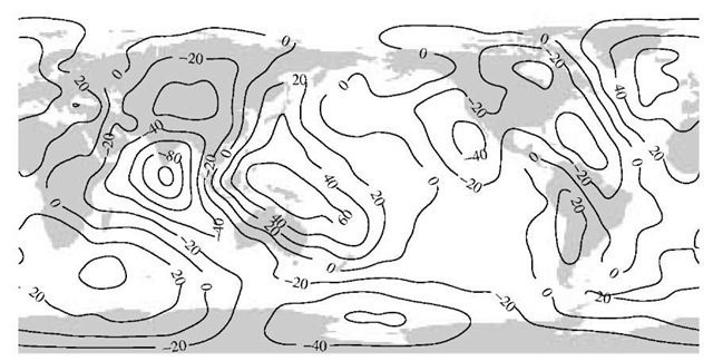
Conceptually, WGS 84 is a very special datum as it includes a model for the gravity field. The description is given by spherical harmonics up to degree and order 180. This adds 32,755 more coefficients to WGS 84 allowing for determination of the global features of the geoid. A truncated model (n = m = 18) of the geoid is shown in Figure 8.11. For a more detailed description; see Anonymous (1997).
In North America the transformation from NAD27 to WGS 84 is given as
A typical datum transformation into WGS 84 only includes changes in the semi-major axis of the ellipsoid and its flattening and three translations of the origin of the ellipsoid.
WGS 84 is a global datum, allowing us to transform between regions by means of GPS. The importance of WGS 84 is undoubtedly to provide a unified global datum.
FIGURE 8.11. The WGS 84 geoid computed for a spherical harmonics expansion including terms with degree and order 18. The contour interval is 20 m.
Time and Coordinate Reference Frames for GPS and Galileo
GPS uses a time reference frame called GPS Time (GPST), which is steered by a real-time representation of Coordinated Universal Time (UTC) produced by the U.S. Naval Observatory. For Galileo an independent time scale, Galileo System Time (GST) will be established. The offset![]() between GPST and GST will probably be in the order of tens of ns.
between GPST and GST will probably be in the order of tens of ns.
A combined GPS and Galileo receiver will correct Galileo pseudoranges to GST and GPS pseudoranges to GPST. The offset![]() between GST and GPST can be estimated as an additional unknown in the position solution. Or equivalently we estimate the receiver clock offset dt to GPST and the receiver clock offset St to GST. Now
between GST and GPST can be estimated as an additional unknown in the position solution. Or equivalently we estimate the receiver clock offset dt to GPST and the receiver clock offset St to GST. Now![]()
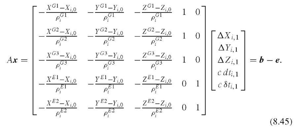
The linearized system of observation equations for three GPS pseudoranges and two Galileo pseudoranges is as follows (the proposed RINEX version 3 uses the letter G for GPS and the letter E for Galileo):
The coordinate reference frame for GPS is WGS 84. In fact, it is a realization of an International Terrestrial Reference Frame. It is realized through Cartesian coordinates and velocities of a global set of sites; these are identical to the tracking stations for GPS. Occasionally, the tracking stations are recoordinated. The latest modification was implemented in GPS week number 1150.
In a similar way, Galileo will use another independent realization (GTRF). In practice, both frames will be the same, but the difference is still a few centimeters, which may be significant for very precise applications.
![tmp2D1307_thumb[2][2][2][2] tmp2D1307_thumb[2][2][2][2]](http://what-when-how.com/wp-content/uploads/2012/02/tmp2D1307_thumb2222_thumb.png)
![tmp2D1317_thumb[2][2][2][2] tmp2D1317_thumb[2][2][2][2]](http://what-when-how.com/wp-content/uploads/2012/02/tmp2D1317_thumb2222_thumb.png)
![tmp2D1332_thumb[2][2][2][2] tmp2D1332_thumb[2][2][2][2]](http://what-when-how.com/wp-content/uploads/2012/02/tmp2D1332_thumb2222_thumb.png)
![tmp2D1338_thumb[2][2][2][2] tmp2D1338_thumb[2][2][2][2]](http://what-when-how.com/wp-content/uploads/2012/02/tmp2D1338_thumb2222_thumb.png)
![tmp2D1340_thumb[2][2][2][2] tmp2D1340_thumb[2][2][2][2]](http://what-when-how.com/wp-content/uploads/2012/02/tmp2D1340_thumb2222_thumb.png)
![tmp2D1343_thumb[2][2][2][2] tmp2D1343_thumb[2][2][2][2]](http://what-when-how.com/wp-content/uploads/2012/02/tmp2D1343_thumb2222_thumb.png)
![tmp2D1350_thumb[2][2][2][2] tmp2D1350_thumb[2][2][2][2]](http://what-when-how.com/wp-content/uploads/2012/02/tmp2D1350_thumb2222_thumb.png)
![tmp2D1356_thumb[2][2][2][2] tmp2D1356_thumb[2][2][2][2]](http://what-when-how.com/wp-content/uploads/2012/02/tmp2D1356_thumb2222_thumb.png)
![tmp2D1358_thumb[2][2][2][2] tmp2D1358_thumb[2][2][2][2]](http://what-when-how.com/wp-content/uploads/2012/02/tmp2D1358_thumb2222_thumb.png)
![tmp2D1359_thumb[2][2][2][2] tmp2D1359_thumb[2][2][2][2]](http://what-when-how.com/wp-content/uploads/2012/02/tmp2D1359_thumb2222_thumb.png)
![tmp2D1374_thumb[2][2][2][2] tmp2D1374_thumb[2][2][2][2]](http://what-when-how.com/wp-content/uploads/2012/02/tmp2D1374_thumb2222_thumb.png)


