2.1
In this section, public switched telephone network (PSTN) and VoIP mapping and different VoIP basic call combinations are given. PSTN-based voice calls and infrastructure have been familiar to users for several decades. Functionally, a user will be using PSTN and VoIP in a similar way. However, several differences between PSTN and VoIP exist in actual implementation and end-to-end transmission. In Table 2.1, some key aspects and functional differences
Table 2.1. PSTN and VoIP Comparison Overview
| Attributes | PSTN | VoIP |
| Major mapping | Digital loop carrier (DLC) is | VoIP CPE provides |
| the intermediate box | functionality of DLC and | |
| between phone and CO and | some functions of PSTN | |
| CO manages call routing | CO | |
| Phones analog | Phone is connected to DLC | CPE is kept within a few |
| termination | through analog two wires. | feet of the phone. Beyond |
| After DLC, digital |i/A-law | CPE, IP packets are sent | |
| samples are sent as bits | ||
| RJ-11 phone | Analog wire of several 1000 | Phone is directly connected |
| connector | feet from DLC is terminated | to VoIP adapter/CPE |
| on wall socket | ||
| Distortions on | Higher distortions due to long | No analog transmission |
| analog line | loop lengths and creates | distortions due to short |
| problem to fax | loop length, which helps | |
| fax calls | ||
| DLC output | DLC may offer different | VoIP CPE provides |
| impedance | impedance to match along | matching impedance |
| with long lines | same as phone | |
| Ring and drive | DLCs support three to five | VoIP CPE drives usually |
| strength | phones, under the | two to three phones, |
| supervision of CO | sometimes under soft- | |
| switch supervision | ||
| Battery voltages | Sometimes higher voltages are | Phone is directly going to |
| provided to compensate for | adapter. Exact voltages | |
| line voltage drops | are maintained | |
| Protection on | Better protection for surges, | This usually stays inside the |
| TIP-RING | short circuits, and lightening | customer location and a |
| minimal protection is | ||
| used | ||
| Line diagnostics | PSTN management system can | A minimal diagnostics are |
| conduct remote telephone | built in to the VoIP CPE. | |
| diagnostics referred to as | Many CPEs do not | |
| GR-909 in North America | implement this feature | |
| Digit detection | Dialed digits from phone are | Dialed digits are detected |
| detected on nearest central | on the VoIP CPE and or | |
| office | soft switch |
Table 2.1. Continued
| Attributes | PSTN | VoIP |
| Call routing, tones, | Call routing and call progress | The VoIP CPE and soft |
| and call features | is created through central | switches decides call |
| office | routing; a direct CPE- to - | |
| CPE call is also possible | ||
| End-to-end voice | Up to DLC, it is analog. From | Compressed voice in |j7A- |
| transmission | DLC, it is a digital ^/A-law | law or low-bit rate codec |
| sample. Digital samples are | samples are packetized | |
| switched in multiple stages | and sent on IP. At | |
| of PSTN on a time division | destination the VoIP | |
| multiplex network | adapter converts packets | |
| to analog signal | ||
| End to end delays | Decided by the physical | Under good network and |
| distance, intra – regional calls | implementations, 50 to | |
| are of 16 ms | 80 ms more than PSTN | |
| calls | ||
| Echo cancellation | Usually not required on | Echo cancellation is always |
| regional calls, and for inter- | required due to long | |
| regional calls, an echo | round – trip delays | |
| canceller is used at selected | ||
| central office nodes | ||
| Clock PPM | DLCs use stratum-3 or better | VoIP CPEs use 30 to |
| clock precision | 50 PPM. Some | |
| deployments use PSTN | ||
| clock precision | ||
| Bandwidth on | 64 kbps | Varies from 16 to 128 kbps |
| TDM networks | depending on the | |
| compression and network | ||
| interfaces | ||
| MOS quality | PESQ – MOS 4.4 | MOS 4.3 to 4.4 with G.711, |
| high compression codecs | ||
| give lower MOS |
Abbreviations: MOS, mean opinion score; PPM, parts per million; PESQ, perceptual evaluation of speech quality; kbps, kilo bits per second.
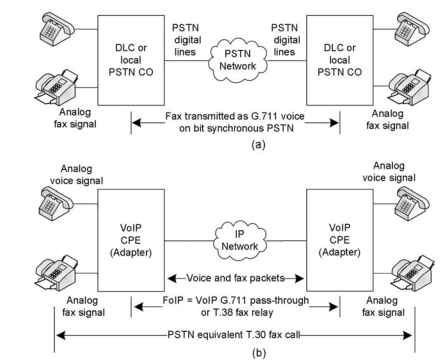
are given. A functional representation of a PSTN-based voice call is given in Fig. 2.1(a). VoIP calls can be mapped very closely to PSTN on an IP network as shown in Fig. 2.1(b). VoIP customer premises equipment (CPE) resides close to the end user of the VoIP service.
2.1.1
CPE and Naming Clarifications of VoIP Systems in this topic
In this topic, CPE, VoIP adapter, and VoIP gateway names are used frequently and interchangeably. A VoIP CPE name is generic in that it accommodates several end-user boxes such as VoIP adapters, integrated access devices (IADs), residential gateways (RGs), home gateways (HGs), terminal adapters (same

Figure 2.1. (a) PSTN voice and fax call; (b) representation of VoIP voice and fax call between two gateways.
as VoIP adapters), wireless fidelity (WiFi) IP phones, IP phones, VoIP soft phones on computers, and any new systems that are positioned directly at the end user. CPE terminals are available to the end user for directly making voice and fax calls.
Some confusion may happen while reading this topic with usage of the names “VoIP gateway” and “voice gateway.” In the early products, the VoIP gateway name was used for a high-channel VoIP-PSTN bridging gateway. Cisco products refer “gateway” to represent a high-channel system that usually resides at the subscriber enterprise or service provider [Donohue et al. (2006)] location. This shared naming occurs because residential gateways and home gateways are end-user CPE boxes, and more often, they are called simply “gateways.” Also, several CPE users are using the VoIP gateway name to refer their CPE box. The CPE terminals with foreign exchange subscriber (FXS), FXS foreign exchange office (FXO) interfaces are referred to as gateways, and stand-alone terminals like IP phones, WiFi handsets, and soft phones are not referred to as gateways.
In this topic, the VoIP gateway name is also used for CPE that is used for FXS and FXO interfaces. Wherever it is required to convey a high-channel gateway of the enterprise or service provider, it is exclusively referred to as
the VoIP-PSTN gateway or as the PSTN-VoIP gateway. The name “gateway” without the prefix of “VoIP-PSTN” or “PSTN-VoIP” is a CPE in this topic.
2.1.2
VoIP End-User Call Combinations
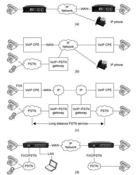
VoIP end- user call combinations vary widely based on the end- user equipment, service provider features, and the operational knowledge of the user. At the functional level, VoIP residential services are used with the following major call combinations. The combinations listed here are time sensitive and may change over time. Figure 2.2 provides functional representations that do not represent a complete deployment infrastructure.
CPE-to-CPE Calls. A CPE-to-CPE VoIP call is shown in Fig. 2.2(a). A voice call originating from one CPE can reach another CPE globally on the VoIP network, assuming the IP network is allowing end-to-end networking functions. This type of call is supported in a controlled way under the supervision of the service provider infrastructure or direct peer-to-peer VoIP calls between two CPEs. A CPE-to-CPE call combination is a true VoIP, and it provides a major benefit in the migration to VoIP
CPE-to-PSTN Calls. A VoIP CPE to the existing PSTN and cell phone calls are shown in Fig. 2.2(b). In Fig. 2.2(b), the function of the VoIP-PSTN gateway is to interface between VoIP and PSTN. This high-channel gateway [Donohue et al. (2006)] handles calls between VoIP and PSTN. The VoIP-PSTN gateway handles several thousand simultaneous calls between VoIP and PSTN. A voice call originating from the CPE can reach an existing PSTN phone and a cell phone through the nearest VoIP-PSTN gateway. The calls are established mainly under the supervision of the service provider infrastructure. On determining the final destination of the VoIP call as a PSTN call, the gateway routes the calls to the PSTN. Calls are also established in the reverse direction from PSTN to VoIP.
PSTN-to-PSTN Calls through VoIP. PSTN-to-PSTN long-distance calls through VoIP are shown in Fig. 2.2(c). A PSTN call can use the VoIP network to route a long-distance call. At both destinations, the local PSTN network is used to complete the call. As an example, to make a call from San Jose to New York using the PSTN and VoIP network, the San Jose PSTN network can reach the gateway closest to San Jose (West coast), and the VoIP call can terminate on the VoIP gateway positioned close (from an operational point of view) to New York (East coast). In general, the VoIP-PSTN gateway establishes connectivity with the existing PSTN network. It performs transcoding and call signaling translation to work between IP and PSTN. Both PSTN clouds are of local regions.
CPE-to-Local PSTN Calls. As shown in Fig. 2.2(d), CPE can provide an additional FXO called as a lifeline connection for local PSTN connectivity.

Figure 2.2. VoIP basic call combinations: (a) CPE-to-CPE VoIP call, (b) CPE-to-CPE and PSTN call through VoIP-PSTN gateway, (c) PSTN-to-PSTN call through VoIP-PSTN gateways at different regions, and (d) CPE calls to PSTN.
FXS can reach a local PSTN through the FXO directly at CPE. It facilitates additional local PSTN-specific services. CPE can also handle VoIP calls
between PSTN and VoIP. The PSTN-supported CPEs with an FXO interface
are also called residential gateways or home gateways.
CPE for Data Service. Data services are also supported on CPE through LAN interfaces in addition to voice. The interfaces include a wired universal serial bus (USB), Ethernet port, or wireless local area network (WLAN). The quality- of- s ervice (QoS) implementation internal to the CPE provides the priority to voice packets to ensure low-delay, real-time operations for voice.
CPE as Mobile Device. A WiFi phone as a limited-range mobile device is in use now. Mobile convergence is now happening that allows VoIP CPE to possess mobile capabilities through various hand- over mechanisms among VoIP, the mobile network, and PSTN.
