A clay nozzle is made by ramming dry nozzle clay against a nozzle mold (Figure 4-1). When the rocket motor is finished, the nozzle mold and another tool, called a core spindle, are removed. The result is a hard, ceramic bulkhead at the rear of the motor, with a central hole for the rocket exhaust. A female, cone-shaped divergent exit taper (Figure 4-2) aids the expansion of the motor’s exhaust into the atmosphere, and this facilitated expansion increases the motor’s exhaust velocity and thrust.
The best material for a nozzle mold is stainless steel. Regular steel is cheaper, but in the presence of the propellant’s oxidizer, a tool made of regular steel will quickly rust if you don’t keep it clean. You can get by with aluminum or brass, but because these metals are soft, a tool made of aluminum or brass will quickly wear out. Wood and plastic will not work, because they are not strong enough to withstand the rigors of the ramming and loading process.
Important note. When shopping for steel, ask for an alloy that is easy to machine. When buying regular steel, ask for “cold rolled” steel. When buying stainless steel, ask for “type 304″. Type 304 stainless is more expensive than cold rolled, but you only need a pound or two. For a job this small, the added cost will amount to a few dollars at most.
Important note. Most metal dealers have bins of what they call “remnants”, which they sell at reduced prices. These are the cutoff scraps left over from large, industrial orders. If you can find what you need in a remnant bin. you’ll save some money.
The following instructions explain the setups and procedures that I use to make a nozzle mold, and topic 5 contains all the drawings of all the molds needed to make all the motors in this topic. In the pages ahead 1 refer to a nozzle mold’s parts, and I’ve illustrated these parts in Figure 4-3. To make a nozzle mold, refer to Figure 4-3. and proceed as follows.
Begin by cutting a piece of round, stainless steel barstock to the appropriate size. The strategy in machine work is to always start with a piece of metal that’s a little bigger than the finished product. Then trim away the excess metal during the machining process. In machine shop jargon, the thing you are machining is called “the workpiece”.
Figure 4-4. The total height from the bottom of the body-to the top of the cone is summed up. The workpiece is trimmed to this length with a series of face cuts.
Figure 4-5. A series of side cuts trims the outside diameter of the step back to the face of the body.
Figure 4-6. Using the cross feed screw, the lathe tool is slowly backed out across the face of the body. This cleans up the body, and machines it to its finished dimension.
Figure 4-7. A series of side cuts generates the outside diameter of the cone’s base, and machines it back to the face of the step.
1. Mount the workpiece in a 3-Jaw lathe chuck, and true up the end with a light facing cut. Then turn it around, and true up the opposite end in the same manner. When mounting it in the chuck this second time, use the following procedure. From the drawing, read the thickness of the nozzle mold’s body, and mount the workpiece so that a little less than that length of material is gripped by the jaws of the chuck.
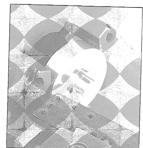
Figure 4-8. Using the cross feed screw, the lathe tool is slowly backed out across the face of the step. This cleans up the step, and machines it to its ‘finished dimension
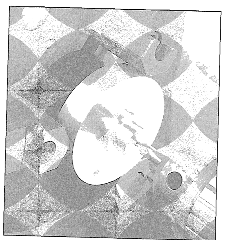
Figure 4-9. With a center drill mounted in the lathe’s tail stock drill chuck, the top of the cone is center-drilled.
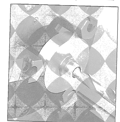
Figure 4-10. The spindle hole is started with a slightly undersize drill.- then finished with the exact size drill indicated in the drawing.
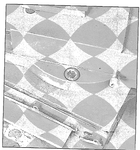
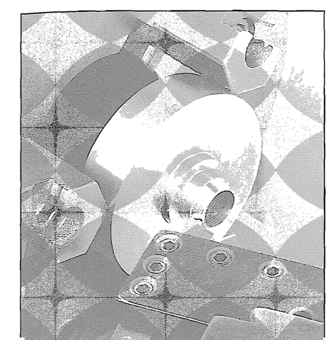
Figure 4-11. The lathe’s compound is set at a 15″ angle, and locked in place. An eyeball setting is good enough.’
l-’
Figure 4-12. The sides of the cone are cut by hand feeding the lathe tool with the lathe’s compound screw.
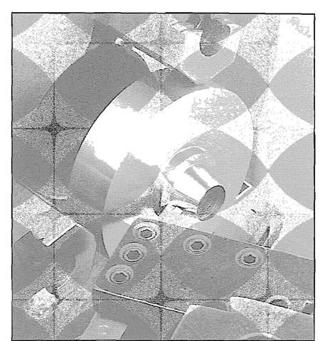
Figure 4-13. When the cone’s base meets the face of the step, the cone is finished.
2. With a series of side cuts, machine the outside diameter of the step back to the front face of the body (Figure 4-5). If the lathe has an adjustable carriage stop, it will be helpful to use it when doing this.
3. With the lathe’s cross feed screw, slowly back the tool out across the face of the body. This cleans up the body, and at the same time, machines the body to its finished dimension (Figure 4-6).
4. With a second series of side cuts, generate the diameter of the base of the cone, and machine it back to the face of the step (Figure 4-7).
5. With the lathe’s cross feed screw, slowly back the tool out across the face of the step. This cleans up the step, and at the same time, machines the step to its finished dimension (Figure 4-8).
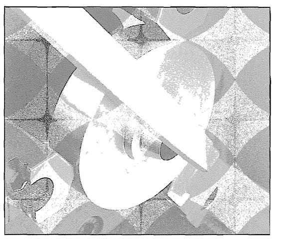
Figure 4-14. The top of the cone, and all sharp edges are deburred with a file.
6. Mount a center drill in the tailstock drill chuck, and center-drill the top of the cone (Figure 4-9). Switch to a slightly undersize drill, and rough-drill the spindle hole (Figure 4-10). Then finish-drill the spindle hole with the exact size drill indicated in the drawing, and use tapping fluid or coolant to produce as smooth a finish as possible.
7. As shown in Figure 4-11. set the lathe’s compound at a 15 degree angle (an eyeball setting is good enough). Cut the sides of the cone by hand feeding with the compound’s lead screw, and use the lathe’s cross feed screw to advance the tool into the work with each succeeding cut. Figure 4-12 shows the work half done. Keep cutting until the base of the cone meets the step (Figure 4-13).
8. With the lathe turned on and the workpiece spinning, deburr the sharp edge at the top of the cone with a fine file (Figure 4-14 ). Then use the file to smooth the other sharp edges. With the completion of this final step, the nozzle mold is finished.
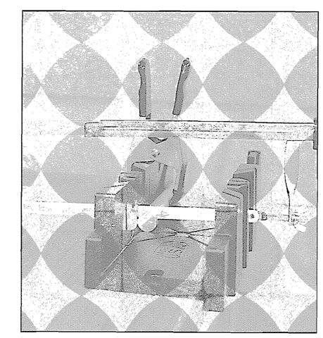
Figure 4-15. Two metal disks are cut with a hacksaw and a /inter box.
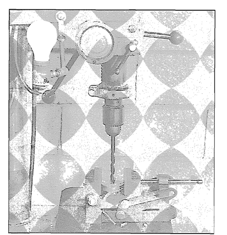
Figure 4-16. A 3/8″ dia. hole is drilled through the center of each disk.
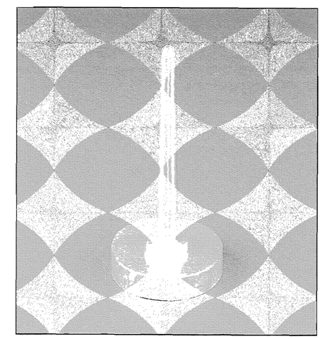
Figure 4-17. The two disks are stacked on the work surface, and the core spindle is inserted.
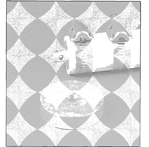
Figure 4-18. The finished motor (in the casing retainer) is lifted off the work surface, leaving the large disk behind.
U Tolerances
Check your measurements with a micrometer or a vernier caliper as you go. A drilled hole is good enough for the spindle hole. An eyeball setting on the compound angle for the cone is fine, and a tolerance of plus or minus .005″ is more than adequate for all the other dimensions. The outside diameter of the body is not critical: it can remain the original o.d. of the metal you started with. Please note that this is not the only way to make a nozzle mold. This is just the way that / do it. If you’re already experienced in machine work, you might prefer another approach.
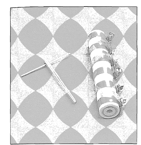
Figure 4-19. With a twisting motion, a T-handle cut from a piece of piano wire pulls out the core spindle.
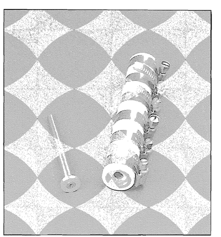
Figure 4-20. The large end of the spindle is used to wiggle out and remove the small disk.
