To make a nozzle mold without a metal lathe, you can improvise. It is not practical to make an divergent taper cone, but you can make a set of centering rings for the core spindle. You’ll need two round pieces of brass, aluminum, or steel of suitable diameter, a drill press, and a bandsaw or a hand operated hacksaw with a miter box. Here’s how to do it.
1. With a hacksaw or a metal cutting bandsaw. cut a 1/8″ thick disk from the end of a piece of 3/4″ dia.. round, metal barstock. Aluminum is the easiest to cut. and though many woodworkers don’t know it. you can cut aluminum on a wood cutting bandsaw with a sharp, standard, wood cutting blade. You can make the cut square by clamping the barstock to the saw’s miter gauge, set at a 90 degree angle. Then, using the same tools and technique, cut a 1/2″ thick disk from a piece of 2″ diameter barstock. If you do it with a hacksaw, clamping the bar into a cheap, carpenter’s miter box (Figure 4-15 ) will steady the saw. and insure that the cut is reasonably straight.
2. Using the best means available, locate the center of each disk. Clamp each disk into a drill press vise, and drill a 3/8″ diameter hole through its center (Figure 4-16 ).
You can now substitute these two rings for the 3/4″ x 3/8″ nozzle mold illustrated in drawing number 98-010 on page 99. Here’s how to use them.
1. Place the large ring on the work surface, and lay the small ring on top of it. Insert the core spindle (Figure 4-17). Press the motor casing (inside the casing retainer) down over the assembly, just as you would if you were using a nozzle mold. Then form the nozzle, and load the motor in the usual manner. Due to the lack of a divergent taper, motors made in this way will take a little more clay, so check your depths as you work, and verify that all the motor’s internal dimensions are correct.
2. When the loading process is finished, lift the motor (in the casing retainer) off the work surface, leaving the large ring behind (Figure 4-18). Using a thick piece of piano wire (aka “model airplane landing gear wire”) as a T-handle. pull out the core spindle (Figure 4-19). With the large end of the core spindle, or a rod of the same diameter, wiggle and pull out the small ring (Figure 4-20). Remove the motor from the casing retainer, and set it on a rack to dry.

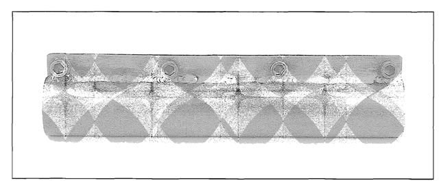
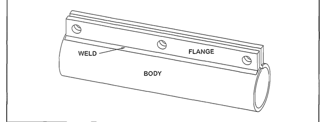
Figure 4-21. A casing retainer keeps the cardboard motor casing from splitting during the loading process. This retainer is made of steel, but you can improvise with plastic pipe and hose clamps.

Figure 4-22. The parts diagram for a casing retainer.
Improvised Centering Rings (Rocket Motor)
Next post: An Improvised Plastic Casing Retainer (Rocket Motor)
Previous post: Nozzle Molds (Rocket Motor)
